Start Measurement
After data processing, the surface data of pin tips, i.e., blobs, are relatively stable and small-sized. Next, you can use the data to measure the height and position of pins.
Measure Pin Height
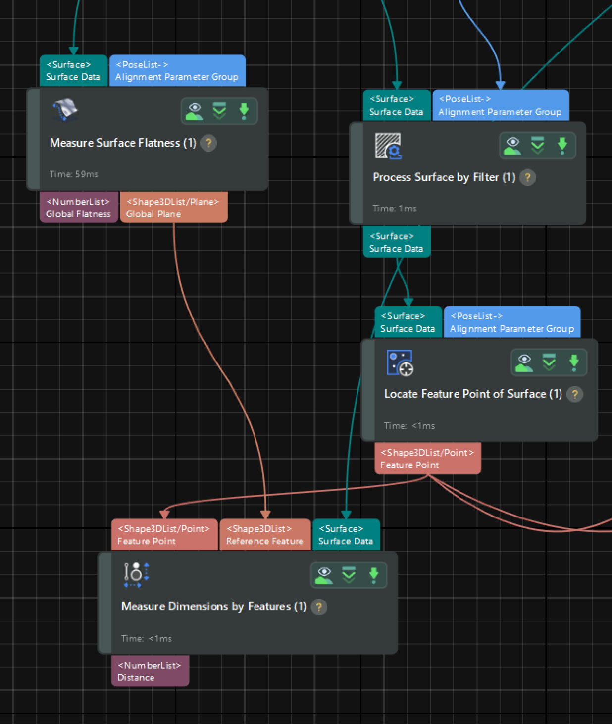
Pin height usually refers to the distance from the tip of a pin to a reference plane (such as the surface of the PCB board). Therefore, you can measure the distance from the center point of blobs to the reference plane to obtain the height of pins.
-
Obtain center points
Use the Locate Feature Point of Surface Step to extract the center points (or feature points) from the surface data of pin tips, which will represent the position of pin tips.
Set the feature point type to Mean in the parameter configuration panel. After the Step is run, it will output the center points of all pin tips.
-
Fit a reference plane
Use the Measure Surface Flatness Step to fit a reference plane.
You can use feature regions to select the flat surface data and set data filtering parameters (as shown below) to filter out noise so that the fitted plane can be stable and accurate.
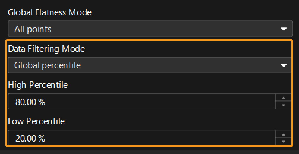
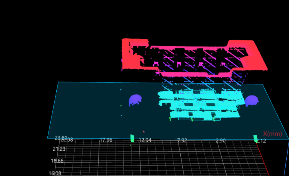
Select Global Plane in the Output section of the Step. After the Step is run, it will output a fitted plane.
-
Measure height
Use the Measure Dimensions by Features Step to measure the pin height.
Select Distance in the Output section of the Step. After the Step is run, it will output the distance from each center point to the reference plane, namely, pin height.
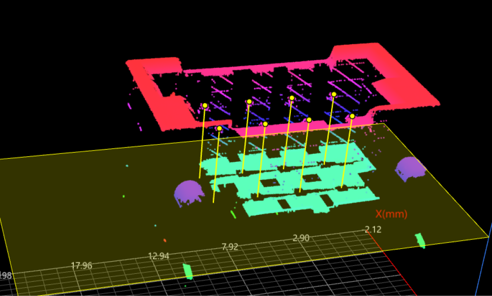
Up to now, you have finished high-precision pin height measurement.
Measure Pin Position
The positions of pins are defined by the horizontal distance from pins to the edges of the connector. Therefore, position inspection requires the measurement of the distance from the center point of the surface data of pin tips to the reference lines fitted using the edge data.
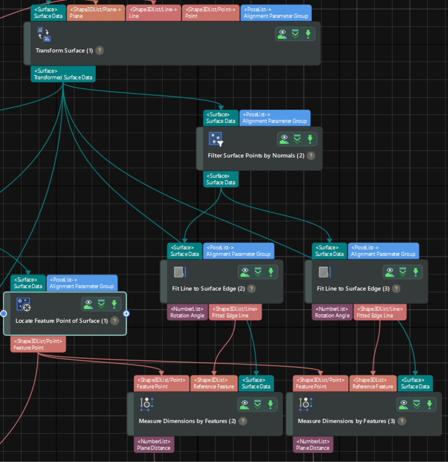
-
Obtain center points
Use the Locate Feature Point of Surface Step to extract the center points (or feature points) from the surface data of pin tips, which will represent the position of pin tips.
Set the feature point type to Mean in the parameter configuration panel. After the Step is run, it will output the center points of all pin tips.
-
Fit edge lines
Similarly, you need to process the surface data so that the fitted lines can be accurate.
-
Use the Filter Surface Points by Normals Step to select the edge data for line fitting and filter out noise.
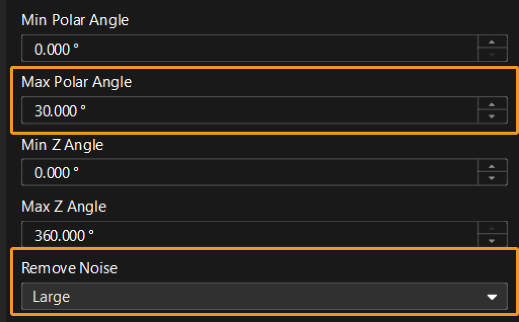
-
Then, use two Fit Line to Surface Edge Steps to fit lines from the processed surface data. In the two Steps, set the search direction to 0° and 90°, respectively, and then set the Outlier Fraction to 15%.
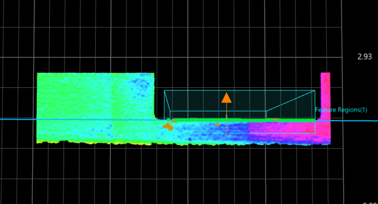
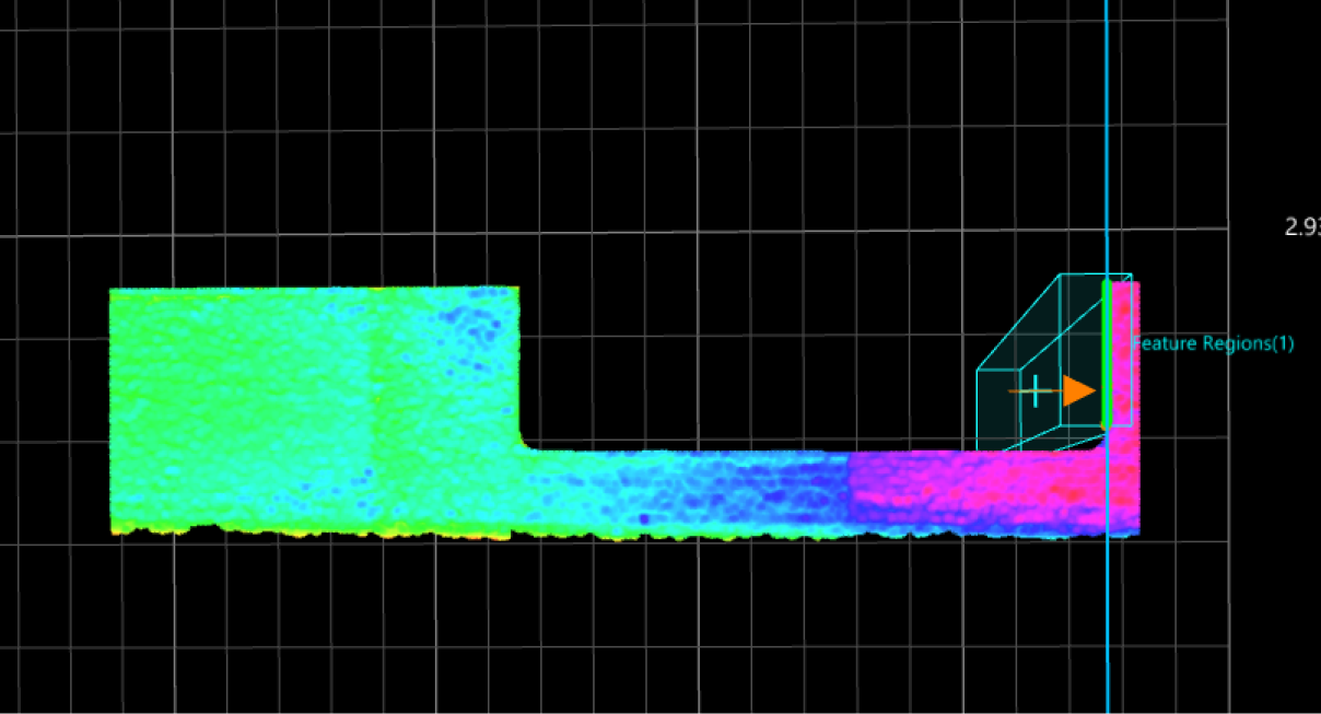
Search direction of 90°
Search direction of 0°
-
-
Calculate the position
Use the Measure Dimensions by Features Step to measure the distance from feature points to the fitted lines. In the Output section of the Step, select Plane Distance.
The data should be projected onto the XOY plane for the calculation of Plane Distance. From a mathematical perspective, two lines can intersect at a single point. Therefore, it is necessary to fit two lines (neither parallel nor coincided) and calculate the distance from pins to the two lines to precisely locate the pins.
Up to now, you have finished high-precision pin position measurement.
Next, you can inspect whether the measured height and position of pins are qualified.