Use Track Line Editor in Mech-MSR
In Mech-MSR, a track refers to the target of measurement, and the track line refers to the path that the track should follow. You can use the track line editor to set one or more track lines for a track.
Prerequisites
When the Measure Surface Track Step is used in a vision project, you can use the track line editor to create and adjust the track lines.
In the parameter configuration panel of this Step, click the Open the editor button under “Track Line Settings” to open the editor.
| Before using the track line editor, make sure that there is valid surface data input in the “Measure Surface Track” Step; otherwise, subsequent operations cannot proceed. |
Workflow
 Create a Track Line Resource
-
Go to Resources in the upper-left corner of the editor and click + New to create a new track line resource.
-
Enter the resource name in the pop-up dialog box, and then click OK.
At this point, the editor will automatically get the input from the Step, and the acquired image will be displayed in the center of the interface.
-
(Optional) Navigate to the upper-right corner of the interface, click Get Step Input to update the image.
-
(Optional) To the right of the image, drag the slider to set the depth range to highlight the key area of the image.
| After selecting a track line resource, you can perform the Rename, Create a Copy, Delete operations via the right-click menu. |
 Draw a Track Line
Use the tools in the toolbar to draw and adjust track lines:
-
 : Select Tool, mainly used to select and adjust a track line.
 -
 : Track Line Drawing Tool, for drawing track lines.
You can draw a track line by the following steps:
-
Select the “Track Line Drawing Tool”
 and then move the cursor to the target track.
 -
Click the left mouse button to set the first vertex, and then move the cursor and continue clicking the left mouse button to add other vertices.
-
Right-click to finish.

|
Navigate to the lower left corner of the interface, and you can find the drawn track line(s) under “List of track lines”. Click ▶ to expand a track line to see all the segments of that track line. (A segment is formed between two adjacent vertices).
 Adjust a Track Line
After drawing a track line, you can perform operations such as move the line, add vertices, and delete vertices.
Detailed operational instructions are as follows:
| Operation | Description |
|---|---|
Move a track line |
|
Select a segment |
You can select a segment in any of the following ways:
|
Add a vertex |
|
Delete a vertex |
|
 Parameter Settings
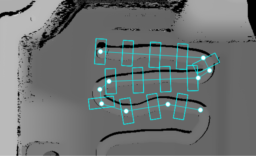
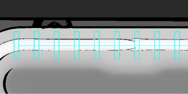
During track line drawing, you can see many “small boxes” evenly spaced along the track line. Each “small box” can be used to extract a section profile from the track.
After selecting a track line in the lower-left corner, you can set the relevant parameters on the far right side of the interface.
Section Profile Settings
Set the parameters related to section profiles to determine the profile span, the width for averaging profiles, and the profile spacing.
| Parameter | Description | ||
|---|---|---|---|
Batch setting |
After the batch setting is enabled, the configured parameters will be applied to the entire track line, and you are not allowed to set parameters for segments. It is enabled by default. If you want to set section profile parameters individually for each segment in the track line, disable Batch setting, expand the track line from the List of track lines, and select a segment to configure it. |
||
Length |
Length refers to the profile span, perpendicular to the track line. The unit is pixels (px). The set length should be slightly greater than the track width (for example, 1.5 times the track width) to ensure the section profile includes some points on the surrounding surface of the track. |
||
Width |
Width refers to the number of pixels considered in the direction perpendicular to profiles. Each point on a profile is the average of the pixels in that column. The unit is pixels (px).
|
||
Spacing |
The distance between adjacent profiles. The unit is pixels (px). |
|
|
Track line settings |
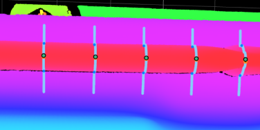
Visual results of the “Measure Surface Track” Step |
As shown in the figure above, you can use the track lines set in the track line editor and run the “Measure Surface Track” Step to obtain the section profile (light blue).
Segment Settings
Navigate to the lower-left corner of the editor, select a track line, and click the ![]() icon to view the segments in the track line.
icon to view the segments in the track line.
By setting the coordinates of the Start point and End point of a segment, you can accurately adjust its position.
|
You can also move the endpoints of a segment in the drawing area. Hover the cursor over an endpoint of the segment, and when the cursor changes to |

