Data Processing
Adjust Top Surface of Refractory Brick to Horizontal Level
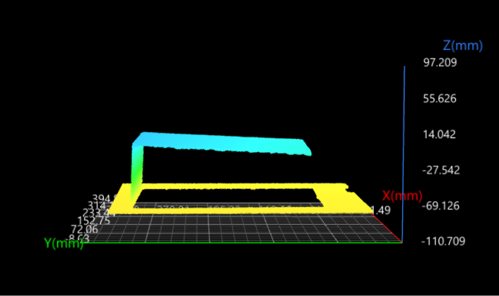
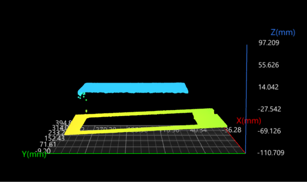
Since the top surface of the incoming refractory brick is tilted, you need to adjust it to a horizontal level (parallel to the XOY plane) so that the subsequent height and side length measurement can be performed accurately and quickly. You can use the Transform Surface Step to transform the surface data to a new reference frame.
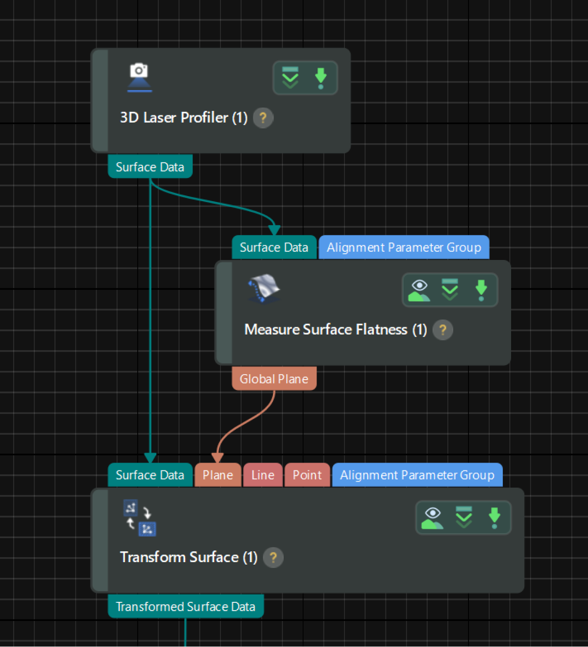
Since the top surface of the refractory brick is flat, the obtained surface data can be transformed into a new reference frame by the Plane method.
The detailed instructions are as follows:
-
Extract a plane feature: Use the Measure Surface Flatness Step to obtain a plane feature, which will be taken as the XOY plane of the new reference frame.
Select the Step and adjust the feature region in the data visualization area to include the top surface of the refractory brick for plane fitting. Then, set the parameters related to plane fitting and data filtering in the parameter configuration panel, as shown below.
For more information on how to set and adjust the feature region(s), see Feature Region. 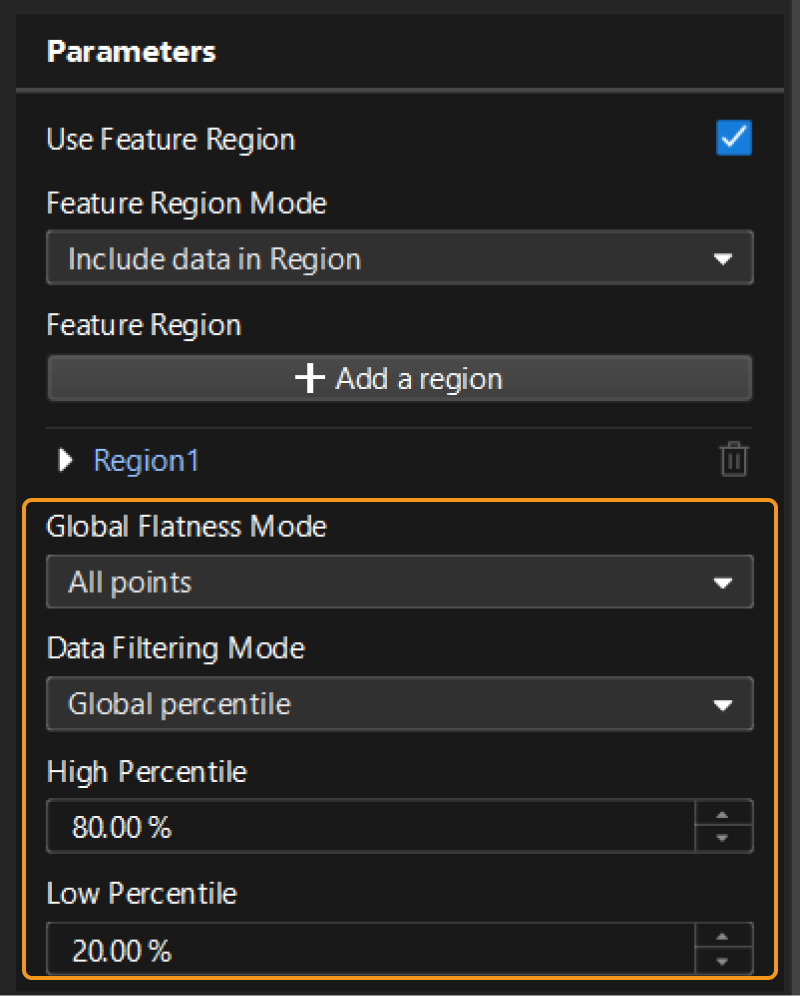
-
Transform reference frame: Run the Transform Surface Step to transform the surface data to the new reference frame. At this time, the top surface of the refractory brick has been adjusted to a horizontal level; the X-axis of the new reference frame is parallel to the original one, and the origin is the projection of the origin of the original reference frame on the new XOY plane.
In the Output Results panel, click
 or
or  to switch the data visualization status, and the data viewer will display the visual content accordingly.
|
|
Tilted top surface |
Transformed data |
- Tuning experience
-
-
Both the Fit Plane to Surface Step and the Measure Surface Flatness Step can be used to rapidly fit a plane, but you can remove noise in data by the latter to obtain a more accurately fitted plane.
-
The running speed of the Transform Surface Step is affected by the Scan Line Count parameter set in Mech-Eye Viewer. When the parameter value is large, the image processing speed of the Step will slow down, which is likely to increase the cycle time.
-
Obtain Corners on Top Surface of Refractory Brick
After obtaining the corners on the top surface of the refractory brick, you can then measure the height by measuring the distance from each corner to the bottom surface of the refractory brick and the length of each side by measuring the distance between adjacent corners.
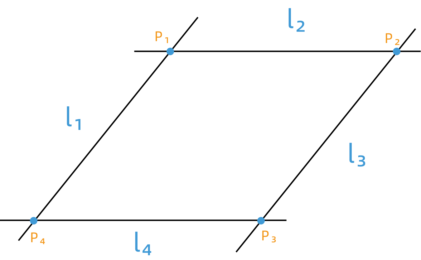
Since corner coordinates cannot be directly and accurately obtained, you can utilize the lines that are fitted to each edge of the top surface to obtain the intersection points of the edges, thereby obtaining accurate locations of corners. The principle is shown in the figure below.
In the project, the data flow connections of Steps are shown in the figure below:
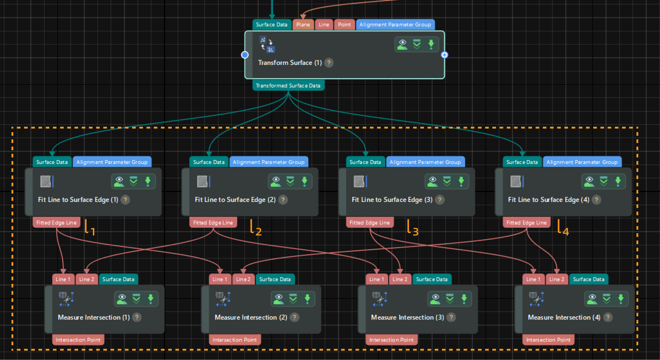
Description of Steps
You can use the Fit Line to Surface Edge Step to obtain the best-fitted lines of each edge on the top surface of the refractory brick. The parameter configuration instructions are as follows in the case of l1.
-
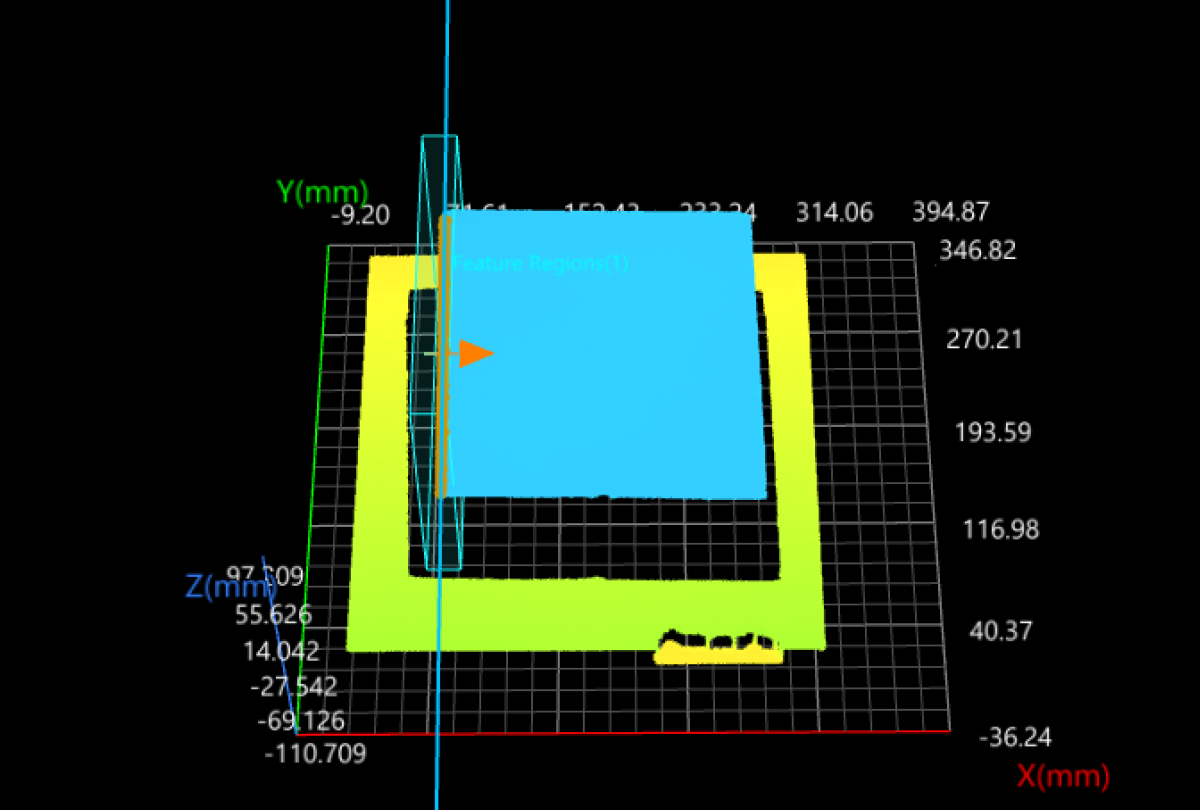
Use a feature region to include the edge data for line fitting.
-
Set the Search Direction to 0°. The search direction should be as perpendicular to the edge (or the fitted line) as possible. After the Step is run, it will detect the points of significant depth or intensity changes along the search direction and use such points to fit the line.
-
Set the Outlier Fraction to 5.000% to eliminate outliers and make the fitted line more accurate.
-
Select the Include Null Points option and set the Null Filling Value of Depth to -10.000.
-
In the Output section of the Step, verify that the Fitted Edge Line item is selected.
After the Step is run, it will output the line fitted to the edge. Repeat the above steps to fit all four lines for the edges of the refractory brick’s top surface.
Once the line fitting for the four edges is finished, you can use the Measure Intersection Step to calculate the intersection points of lines.
The parameter configuration instructions on the Measure Intersection Step are as follows in the case of the intersection of l1 and l2.
-
Set Intersection Type to Line and line.
-
Set Projection Mode to XOY plane.
Two non-parallel lines must be projected onto a plane to ensure they can intersect at a single point. -
In the Input section or the graphical programming workspace, ensure that the lines input into the Step can produce an intersection point, and the intersection point is the point of the target corner.
-
In the Output section, verify that the Intersection Point item is selected.
After the Step is run, it will output the intersection point of the two lines.
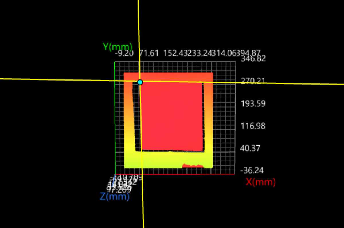
Repeat the above steps to obtain the locations of the four corners on the top surface of the refractory brick.
Next, you can use the obtained corners to measure corner height and side length.
