Blob Analysis
Description
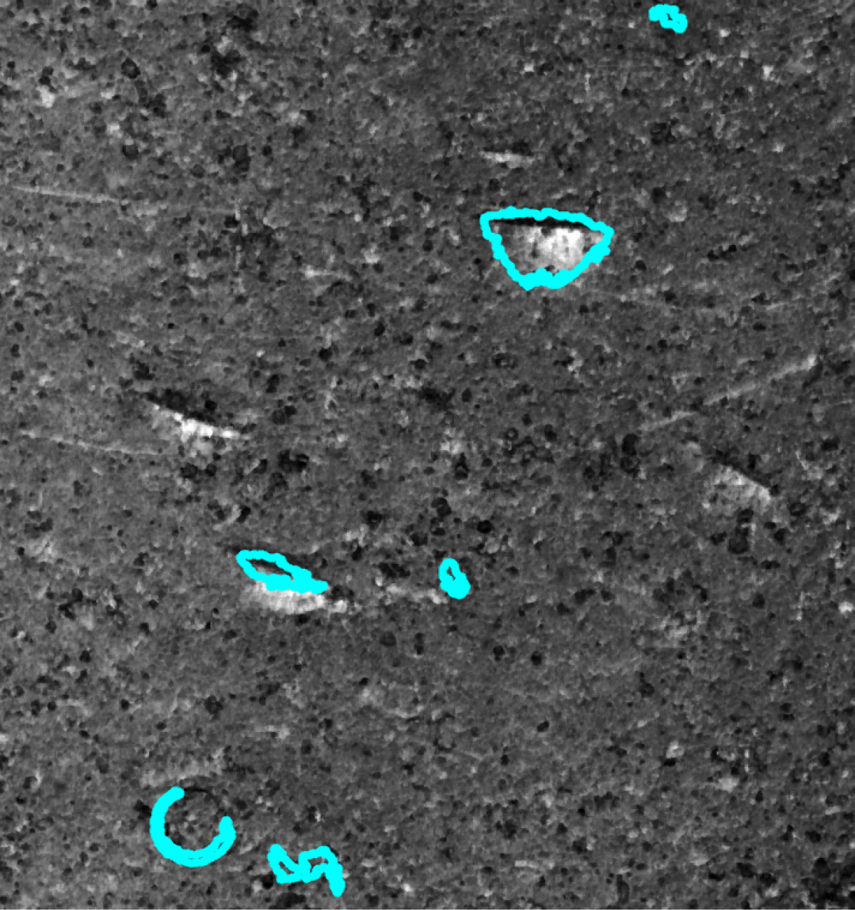
This Step is used to detect defects on a surface based on a depth map or an intensity image. In addition, it can extract targets from the surface.
Workflow
The process of configuring this Step is as follows:
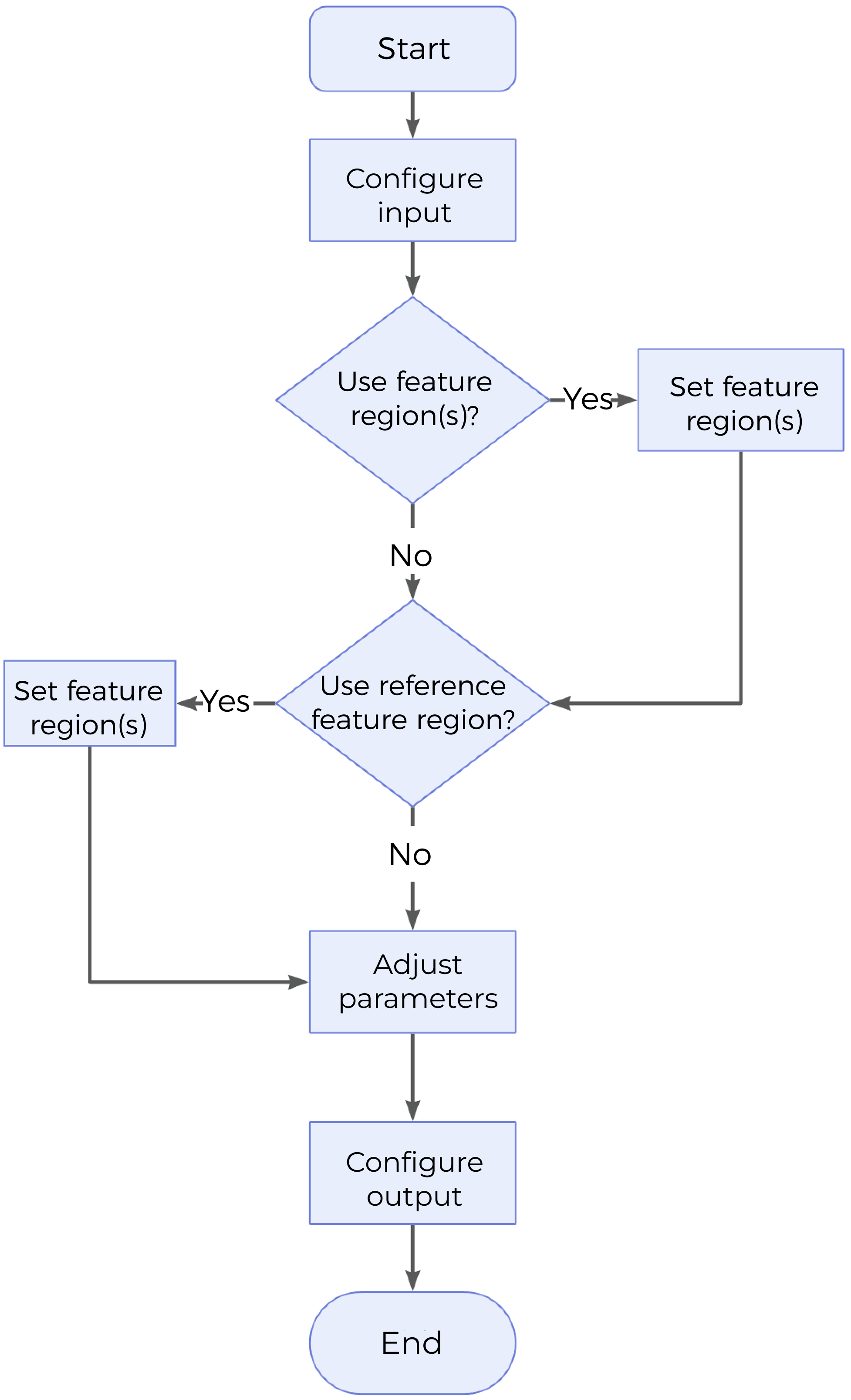
-
Configure the input. Connect the ports manually or select the input(s) under Input in the parameter configuration panel.
-
Determine whether to use feature regions.
-
Determine whether to use reference region.
-
Set other parameters.
-
Select the desired output items under Output. For an expandable output item, click ▶ and configure the Lower Limit and Upper Limit values to set the acceptable range.
Parameter Description
| Parameter | Description | ||
|---|---|---|---|
Use Intensity Image |
Once this option is selected, the intensity image will be used together with the depth map for Blob analysis. It is not checked by default. |
||
Use Feature Regions |
Use feature region(s) to define the region where Blob analysis will be performed. When this parameter is not selected, this Step uses the entire surface data.
|
||
Reference Type |
Use this parameter to select the reference for Threshold Settings.
|
||
Threshold Settings |
Refer to Threshold Settings. |
||
Opening Operation Settings |
|||
Use Area Filter |
Once this parameter is selected, only blobs with areas between Min Area and Max Area will be retained. Selected by default.
|
||
Use Aspect Ratio Filter |
Once this option is selected, only blobs with aspect ratios between Min Aspect Ratio and Max Aspect Ratio will be retained. It is not selected by default. |
||
Use Circularity Filter |
Once this option is selected, only blobs with circularity between Min Circularity and Max Circularity will be retained. It is not checked by default. |
||
Use Convexity Filter |
Once this option is selected, only blobs with convexity between Min Convexity and Max Convexity will be retained. It is not checked by default. |
||
Ordering By |
This parameter specifies the rules for ordering the output blobs. Options: Position (X increasing), Position (X decreasing), Position (Y increasing), Position (Y decreasing), Area (Large to small), Area (Small to large), Row-wise, Column-wise |
||
Row Height or Column Width |
|
||
Blob Search Mode |
This parameter defines the mode of searching the blobs.
|
||
Merge Blob Image |
This parameter determines whether to merge blobs in the output.
|
||
Max Number of Output Blobs |
The maximum number of blobs that can be output after the Step is run. It also corresponds to the upper limit of parameters such as the center point, area, and surface. Default value: 200 |
||
Minimum Blob Distance |
Used to set a minimum distance between neighboring blobs to prevent the detected blobs from being too close to each other. The processing logic is as follows:
|
Threshold Settings
| Parameter | Description |
|---|---|
Threshold Filter |
Determines whether data above or below the threshold are considered blobs.
|
Height Threshold |
Defines the threshold above or below which data are considered blobs. The set value is the minimum or the maximum height of data points that will be considered part of a blob.
|
Intensity Threshold |
Defines the threshold above or below which data are considered blobs. The set value is the minimum or the maximum intensity of data points that will be considered part of a blob. This parameter will be displayed and then requires configuration when Use Intensity Image is selected. |
Opening Operation Settings
| Parameter | Description | ||
|---|---|---|---|
Open Kernel X / Y |
The X and Y kernel size, respectively, for morphological opening to remove small areas of data. Use these settings, for example, to remove bridges between areas to properly isolate them or to remove small areas entirely. Default value: 3 px
|
Output Description
Check the output item to add it to the Step, and the corresponding data will be output after the Step is run. You can select the output according to the actual measurement requirements.
|
If you select an expandable output item, you must expand it by clicking ▶, and then set the Lower Limit and Upper Limit values to determine the acceptable range. If the output value falls within the acceptable range, the measurement item is judged as passing (OK), or else it is judged as failing (NG). |
| Output Item | Description |
|---|---|
Blob Count |
The number of identified blobs. |
Center X of Blob(n) |
The X position of the center of mass of each blob. |
Center Y of Blob(n) |
The Y position of the center of mass of each blob. |
Mean Height of Blob(n) |
The mean height of data points in each blob. |
Min Height of Blob(n) |
The minimum height of data points in each blob. |
Max Height of Blob(n) |
The maximum height of data points in each blob. |
Width of Blob(n) |
The width of the bounding box that encapsulates each blob, i.e., the short edge. |
Length of Blob(n) |
The length of the bounding box that encapsulates each blob, i.e., the long edge. |
Area of Blob(n) |
The area of each blob. |
Center of Blob(n) |
The center of mass of each blob. |
Blob(n) Surface |
The surface data corresponding to each blob. |
Troubleshooting
|
CV-W2901
Error: The set height threshold is invalid.
Solution: Reset Height Threshold to make sure it works.
CV-W2902
Error: The selected reference region is invalid, or the reference plane cannot be used in the grayscale mode.
Possible causes:
-
Reference Type is not configured properly.
-
After selecting the “Use Intensity Image” option, the reference plane cannot be used.
Solution:
-
Configure Reference Type correctly.
-
Unselect the “Use Intensity Image” option, or choose another reference type after selecting the option.
CV-W2903
Error: The input reference plane is invalid.
Possible cause: The parameters related to the reference plane are not set properly.
Solution: Check the parameters related to the reference plane and ensure that the input reference plane is valid.
CV-W2904
Error: The “Kernel Size” value of the selected filter should exceed 0.
Possible causes: The “Kernel Size” value is less than or equal to 0.
Solution: Adjust the “Kernel Size” to ensure that it is greater than 0.
CV-W2905
Error: No blobs detected.
Possible causes:
-
No blob exists within the feature region.
-
Height Threshold is not set properly.
Solution:
-
Check and adjust the feature region to ensure that blobs are present in it.
-
Reset Height Threshold to ensure that the number of blobs above or below (as configured) the threshold is not 0.