Fit Circle to Surface Edge
Basic Concepts
Calipers, circular path, edge points
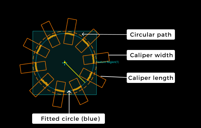
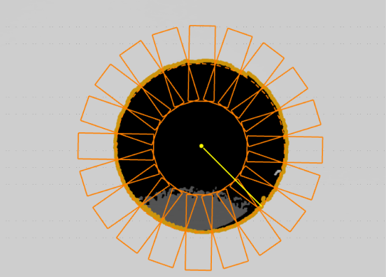
The Step will generate a circular path on the basis of the set feature region, which takes the width (or length, the same) of the feature region as the diameter and the center point as the circle center. Calipers are then placed along the circular path. They are evenly spaced and arranged radially, with their centers on the circular path. In each caliper, profiles are extracted along the length of the caliper based on the specified profile spacing. From each profile, points that meet requirements are detected and marked as edge points. Finally, these edge points will be used to fit a circle.
|
As shown in the figure, the brownish-yellow dots at the edge in the calipers represent the edge points, and the bright yellow line represents the radius of the fitted circle. |
In summary, the basic concepts you should grasp while using this Step are as follows:
-
Caliper
The calipers will be evenly spaced along the circular path. Within each caliper, several profiles (not displayed) are extracted along the caliper’s length at the specified spacing.
-
Circular path
The circle that takes the width (or length, the same) of the feature region as the diameter and the center point as the circle center, which is used for determining the positions of calipers.
If no feature region is set, the diameter of the circular path will be equal to the shorter side of the image’s bounding box, with the center of the circle located at the center of the bounding box. -
Edge point
Points that meet the parameter requirements are detected from the profiles in each caliper and are used for circle fitting.
Workflow
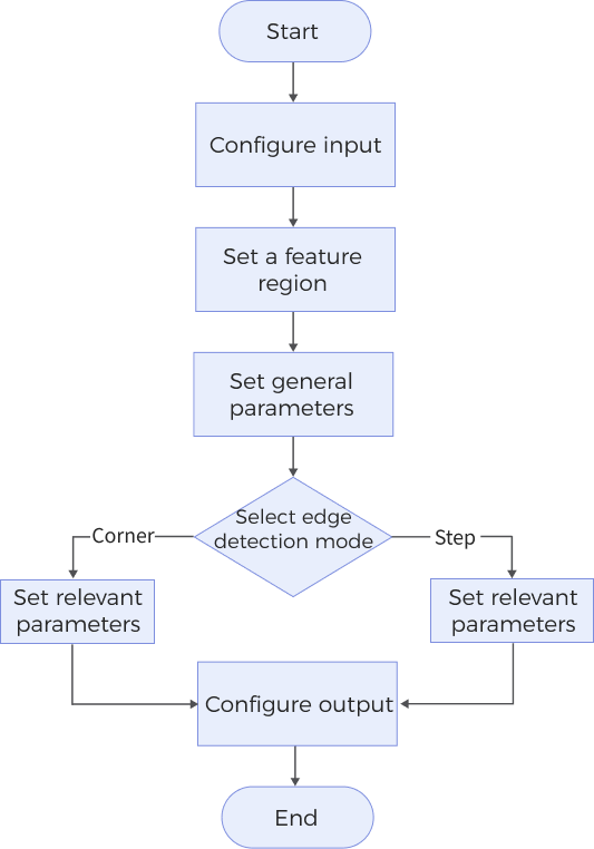
The process of configuring this Step is as follows:
-
Configure the input. Connect the Step ports in the graphical programming workspace or select the input under Input in the parameter configuration panel.
-
Set a feature region, and then set the general parameters.
-
According to the selected edge detection mode, set the relevant parameters for either step edges or corner edges.
-
Select the desired output items under Output. For an expandable output item, click ▶ and configure the Min and Max values to determine the acceptable range for the item.
Parameter Description
General Parameters
| Parameter | Description | ||
|---|---|---|---|
Use Intensity Image |
Select this option to use the intensity image for edge detection when the target detection region is flat, and the color differences in the region are prominent. Once selected, the Step uses the intensity image for circular edge detection and circle fitting; otherwise, the Step uses the depth map by default. |
||
Use Feature Region |
When this parameter is not selected, the Step uses the entire surface data to detect the circular edge and fit the circle. When selected, the Step only uses the data within the feature region for detection and fitting. See Feature Region to learn about how to adjust a feature region. |
||
Use Masks |
After selecting this option, you can set 1 to 4 mask regions to block out part of the data. Data within the mask regions is excluded from circular edge detection and fitting. |
||
Start Angle |
Set the angle to determine the position of the first caliper, and the remaining calipers will be placed counterclockwise at equal intervals according to relevant settings. Interval between calipers = Angle Span ÷ Caliper Count. After the start angle is set, the first caliper will be placed at half an interval angle away from the start angle. Then, the remaining calipers are placed sequentially in a counterclockwise direction at the specified intervals. |
||
Angle Span |
The angle range for evenly arranging the specified number of calipers.
|
||
Caliper Count |
The number of calipers that need to be evenly placed along the circular path. |
||
Caliper Length |
The caliper’s length direction is perpendicular to the tangent to the circular path at the caliper’s center. |
||
Caliper Width |
The caliper’s width direction parallels the tangent to the circular path at the caliper’s center. |
||
Search Direction |
The direction for detecting edge points. The Step will extract profiles along the search direction in the calipers to detect edge points. Value list: Outward, Inward. |
||
Circle Fitting Method |
The method for fitting a circle, which can be used to calculate and assess the roundness of a fitted circle.
|
||
Outlier Fraction |
The percentage of outlier points to be removed during circle fitting. Only visible when the “Circle Fitting Method” is Least square circle (LSC). |
||
Profile Spacing |
The distance between adjacent profiles in the calipers. If the set spacing is less than the pixel width of a pixel, the Step will take the pixel width as the profile spacing.
|
||
Profile Averaging Width |
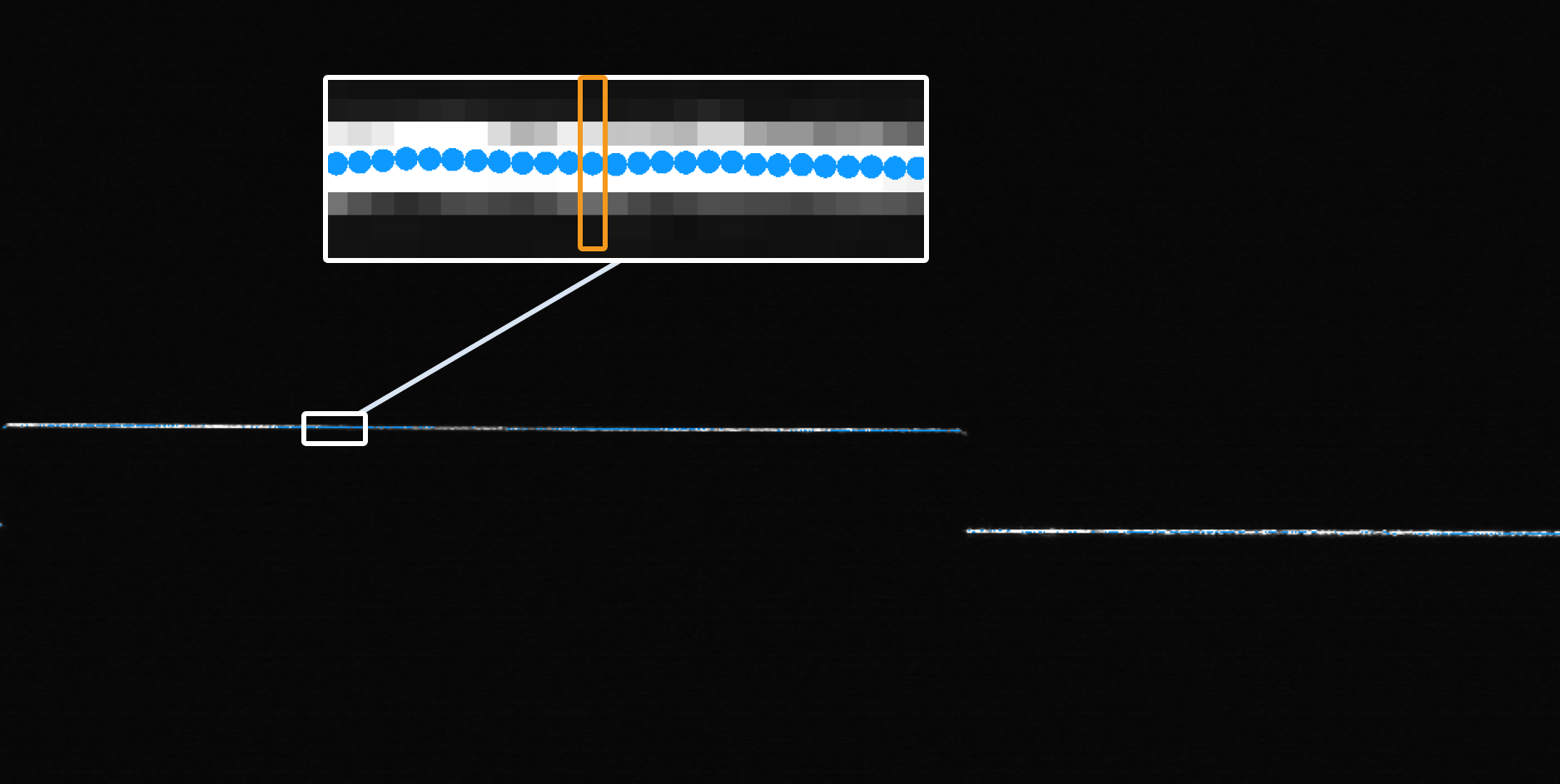
The size of the windows for calculating the average of data points along the direction perpendicular to the profile to obtain a smoother profile and thus reduce the impact of noise. When it is set to 0, no averaging operation will be performed on the profiles.
|
||
Edge Detection Mode |
The depth or intensity changing mode of data points at the edge.
|
||
Show Detail |
Select this parameter to display the calipers and circular path in the visualization window. |
Step Edge Parameters
Set the parameters below when you set the edge detection mode to Step.
| Parameter | Description | ||
|---|---|---|---|
Window Size for Profile Smoothing |
The window size for filtering profiles along the search direction (the direction of profiles). After filtering, the profiles will be smoother. When it is set to 0, no filtering will be performed on the profiles along the search direction. 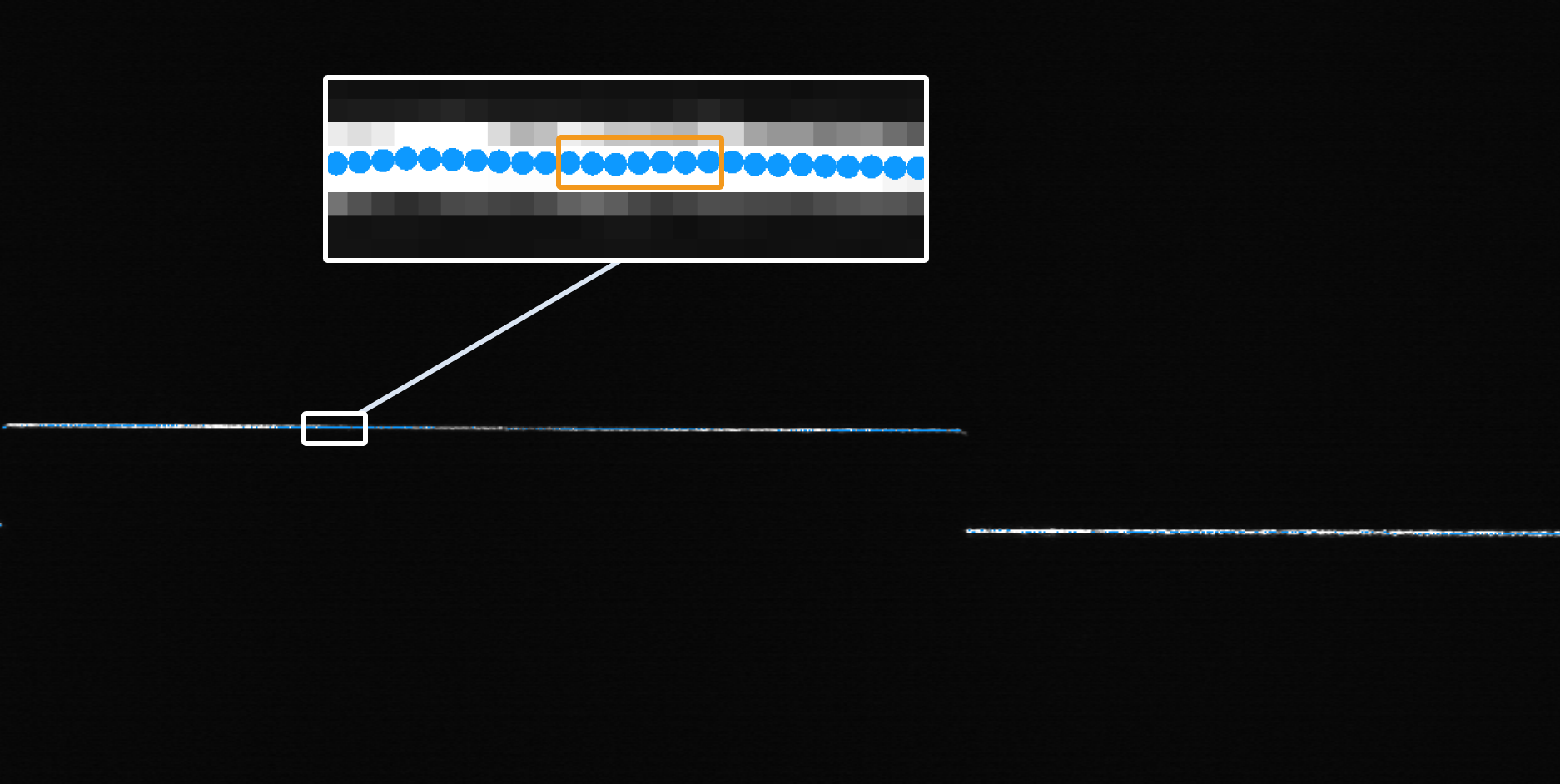
|
||
Gap Filling Threshold |
The data points on a profile may have gaps due to occlusion. When the size of a gap on a profile is less than or equal to the set threshold, the nearest valid point from the lower side of the gap is used to fill it. When the gap size exceeds the set threshold, it remains as null point(s). 
|
||
Include Null Points |
Use this parameter to determine whether to include null points or not in the edge detection process. (Null points are points without depth or intensity information.) Once this parameter is selected, set Null Filling Value of Depth.
|
||
Null Filling Value of Depth |
A depth value for filling null points. Only needs to be set after Include Null Points is selected. |
||
Null Filling Value of Intensity |
An intensity value for filling null points. Only needs to be set after both Use Intensity Image and Include Null Points are selected. |
||
Step Width |
The width of the step on a profile. When the step on a profile is a slope, set this parameter can help you accurately measure the step height and locate the position of the edge.
|
||
Step Direction |
The step direction along the search direction. Value list: Rising, Falling, Rising or falling. |
||
Step Type |
Set the type of step that will be selected from each profile. Value list: Best, First, Last. |
||
Absolute Threshold |
The minimum height variation for a potential step on a profile. A step that satisfies the absolute threshold can produce an edge point. When the parameter Use Intensity Image is selected, absolute threshold means the minimum intensity variation for a potential step on a profile. |
||
Use Relative Threshold |
Use this parameter to determine that a step is valid if the height (or intensity) change of the step is not less than the set percentage of the maximum change found on a profile. Once this parameter is selected, set Relative Threshold.
|
||
Relative Threshold |
Only visible when Use Relative Threshold is selected. |
Corner Edge Parameters
Set the parameters below when you set the edge detection mode to Corner.
| Parameter | Description | ||
|---|---|---|---|
Corner Type |
Select a proper corner type from the drop-down list to determine the edge point. Value list: First, Last, Top, Bottom, Best. |
||
Epsilon |
This parameter reflects the sensibility to the change of the profile shape. A larger value means that fewer points can meet the requirements, and thus it is more challenging to detect corners.
|
Output Description
Select the output item(s) to add the output port(s) to the Step, and the corresponding data will be output after the Step is run. You can select the output according to the actual measurement requirements.
|
If you select an expandable output item, you should expand it by clicking ▶, and then set the Min and Max values to determine the acceptable range. If the output value falls within the acceptable range, the measurement item is judged as passing (OK), or else it is judged as failing (NG). |
| Output item | Description | ||
|---|---|---|---|
Circle Center X |
X value of the center of the fitted circle. |
||
Circle Center Y |
Y value of the center of the fitted circle. |
||
Radius |
The radius of the fitted circle. |
||
Roundness |
The degree to which the fitted circle approximates the ideal circle. A smaller value indicates a closer approximation, meaning the fitted circle is more accurate. |
||
Min Error |
The error value of the edge point farthest within the fitted circle, which is a negative number. |
||
Max Error |
The error value of the edge point farthest outside the fitted circle, which is a positive number. |
||
Center of Fitted Circle |
The center of the fitted circle. |
||
Fitted Circle |
The circle fitted to the circular edge.
|
||
Min Error Point |
The point corresponds to Min Error. |
||
Max Error Point |
The point corresponds to Max Error. |
Troubleshooting
|
CV-W3401
Error: The “Profile Spacing” value is not within the valid range.
Possible cause: The parameter value is less than 0 or greater than the length of the longest side of the image.
Solution: Ensure the parameter value is greater than or equal to 0 and less than the length of the longest side of the image.
CV-W3402
Error: The set “Window Size for Profile Smoothing” is invalid.
Possible causes:
-
The parameter value is less than 0 or greater than the length of the longest side of the image.
-
The parameter value is greater than the caliper length.
Solutions:
-
Ensure the parameter value is greater than or equal to 0 and less than the length of the longest side of the image.
-
Ensure the parameter value is less than the caliper length.
CV-W3403
Error: The set “Step Width” is invalid.
Possible causes:
-
The parameter value is less than 0 or greater than the length of the longest side of the image.
-
The parameter value is greater than the caliper length.
Solutions:
-
Ensure the parameter value is greater than or equal to 0 and less than the length of the longest side of the image.
-
Ensure the parameter value is less than the caliper length.
CV-W3404
Error: The set “Gap Filling Threshold” is invalid.
Possible cause: The parameter value is less than 0 or greater than the length of the longest side of the image.
Solution: Ensure the parameter value is greater than or equal to 0 and less than the length of the longest side of the image.
CV-W3405
Error: The set “Caliper Width” is invalid.
Possible cause: The parameter value is less than or equal to 0, or it is greater than the length of the longest side of the image.
Solution: Ensure the parameter value is greater than 0 and less than the length of the longest side of the image.
CV-W3406
Error: The set “Caliper Length” is invalid.
Possible cause: The parameter value is less than or equal to 0, or it is greater than the length of the longest side of the image.
Solution: Ensure the parameter value is greater than 0 and less than the length of the longest side of the image.
CV-W3407
Error: No edge points detected.
Possible causes:
-
The calipers are not set properly.
-
“Absolute Threshold” and “Relative Threshold” are too large.
Solutions:
-
Adjust the caliper settings to ensure edge points can be detected from the calipers.
-
Lower “Absolute Threshold” and “Relative Threshold” values.
CV-W3408
Error: The “Outlier Fraction” value is outside of the valid range.
Possible cause: The parameter value is less than 0 or greater than 100%.
Solution: Make sure the parameter value is within 0–100%.
CV-W3409
Error: The “Profile Averaging Width” value is outside of the valid range.
Possible causes:
-
The parameter value is less than 0 or greater than the length of the longest side of the image.
-
The parameter value is greater than the caliper width.
Solutions:
-
Ensure the parameter value is greater than or equal to 0 and less than the length of the longest side of the image.
-
Lower the parameter value or raise the caliper width to ensure that the parameter value is less than the caliper width.
CV-W3410
Error: The “Caliper Count” value is outside of the valid range.
Possible cause: The parameter value is less than 1 or greater than or equal to 1000.
Solution: Make sure the parameter value is within 1–1000.
CV-W3411
Error: The “Start Angle” value is outside of the valid range.
Possible cause: The parameter value is less than −180° or greater than 180°.
Solution: Make sure the parameter value is within −180°–180°.
CV-W3412
Error: The “Angle Span” value is outside of the valid range.
Possible cause: The parameter value is less than 10° or greater than 360°.
Solution: Make sure the parameter value is within 10°–360°.
CV-W3413
Error: The set “Circle Fitting Method” is invalid.
Solution: Select a valid circle fitting method from the drop-down list.
CV-W3414
Error: The “Null Filling Value of Intensity” is outside of the valid range.
Possible cause: The parameter value is less than 0 or greater than 255.
Solution: Make sure the parameter value is within 0–255.
CV-W3415
Error: The “Null Filling Value of Depth” is outside of the valid range.
Possible cause: The parameter value is less than −10000 or greater than 10000.
Solution: Make sure the parameter value is within −10000–10000.
CV-W3416
The “Epsilon” value is outside of the valid range.
Possible cause: The parameter value is less than 0.
Solution: Make sure the parameter value is greater than or equal to 0.
CV-W3417
Error: The set “Corner Type” is invalid.
Solution: Select a valid corner type from the drop-down list.
CV-W3418
Error: The “Absolute Threshold” value is outside of the valid range.
Possible cause: The parameter value is less than 0 or greater than 255.
Solution: When the “Use Intensity Image” parameter is selected, ensure the absolute threshold is within 0–255.
CV-W3419
Error: The “Absolute Threshold” value is outside of the valid range.
Possible cause: The parameter value is less than 0 or greater than 10000.
Solution: Make sure the parameter value is within 0–10000.
CV-W3420
Error: The “Relative Threshold” value is outside of the valid range.
Possible cause: The parameter value is less than 0 or greater than 1.
Solution: Make sure the parameter value is within 0–1.
CV-W3421
Error: The set “Edge Detection Mode” is invalid.
Solution: Select a valid edge detection mode from the drop-down list.
CV-W3422
Error: The set “Search Direction” is invalid.
Solution: Select a valid search direction from the drop-down list.
CV-W3423
Error: The set “Step Direction” is invalid.
Solution: Select a valid step direction from the drop-down list.
