Obtain Results
Obtain Inspection Result of Pin Height
After pin height measurement, the acceptable height range for pins can be determined based on actual requirements. Mech-MSR will evaluate the measured height against the set range to determine whether it is within the acceptable limits, and the height inspection result will be output accordingly.
The detailed instructions are as follows:
-
Click the Measure Dimensions by Features Step in the Measure Pin Height process.
-
In the Output section of the Step, expand Distance to set the acceptable height range of pins.
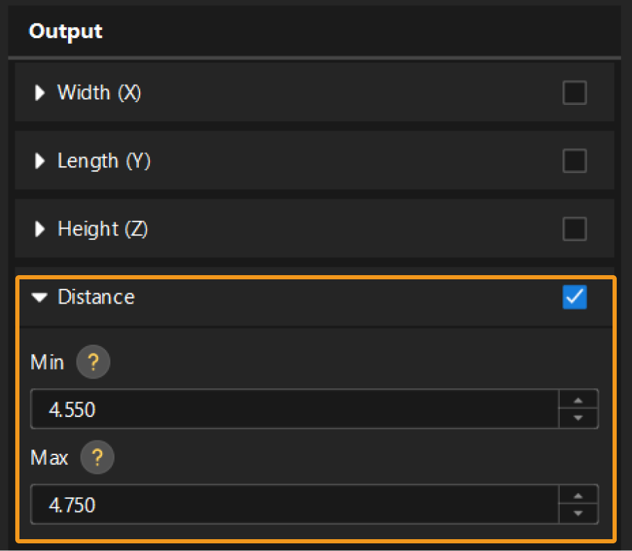
-
Run the Step, and you can check the inspection result of pin height in the Output Results panel at the bottom of the visualization area.

Measured values of pin height all fall within the acceptable range, and thus the inspection result of the output item is OK.
Obtain Inspection Result of Pin Position
It is impossible to set a unified acceptable range for multiple pins as the distance to the reference lines varies. Therefore, you need to use the Evaluate Values in List Step to set an acceptable range for each pin.
| The Evaluate Values in List Step can only take zero-dimensional data, while the measured plane distance is a one-dimensional list. Thus, you need to use the Extract Data Step for dimensionality reduction. |
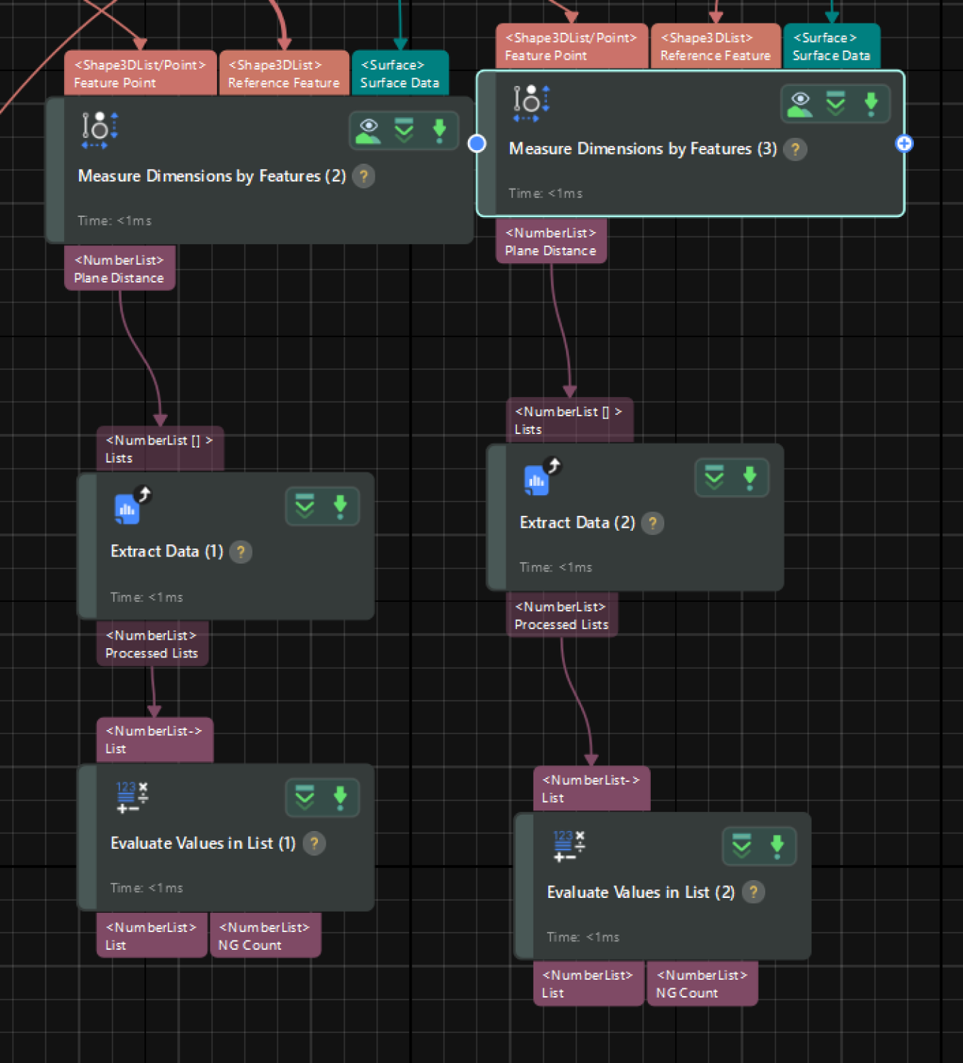
The detailed instructions are as follows:
-
In the Parameters section of the Extract Data Step, set the “Dimension” to 1, and use the range to extract the distance of the eight pins to the reference line.
-
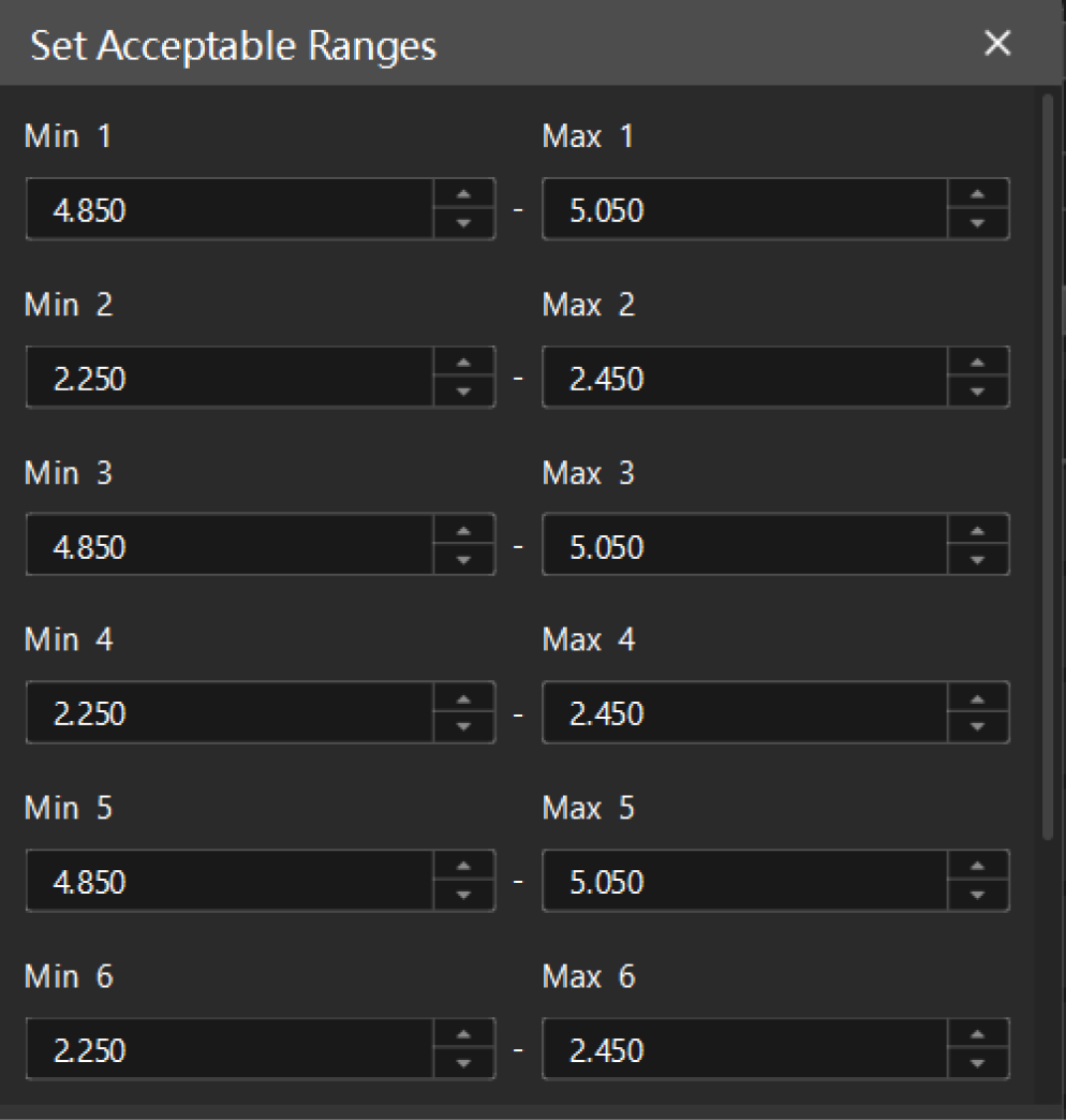
In the Parameters section of the Evaluate Values in List Step, set the “Evaluation Mode” to Custom, and accurately enter the number of measured values, i.e., 8. Then, open the editor to set acceptable distance range for each pin.
-
Finally, in the Output section of the Evaluate Values in List Step, select NG Count, and set both the “Max” and “Min” of the item to 0, namely, no NG value.
Run the Step, and you can check the inspection result of pin position in the Output Results panel at the bottom of the visualization area.

No NG values detected, and thus the inspection result of the output item is OK.
Obtain Inspection Result of Connectors
The inspection result of connectors should consider both pin height and pin position results, that is, the overall judgment result of the project. Click the Output Management button from the toolbar of the home interface to set quality judgment rules for the project.
Select the project under the Quality judgment tab, set Judgment type to Comprehensive, and select the output items corresponding to the above two inspection results.
Example:
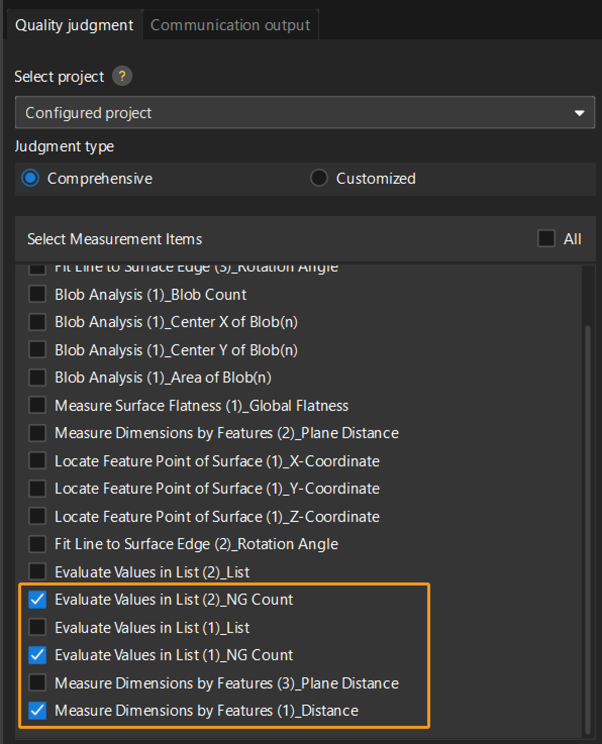
Then, click the Apply button to save the settings. Run the project, and you will obtain the judgment result of the project in the upper-left corner of the graphical programming workspace.
|
For more information, see Configure the Comprehensive Judgment Rule for the Project. |
(Optional) Send Measurement and Inspection Results to External Devices
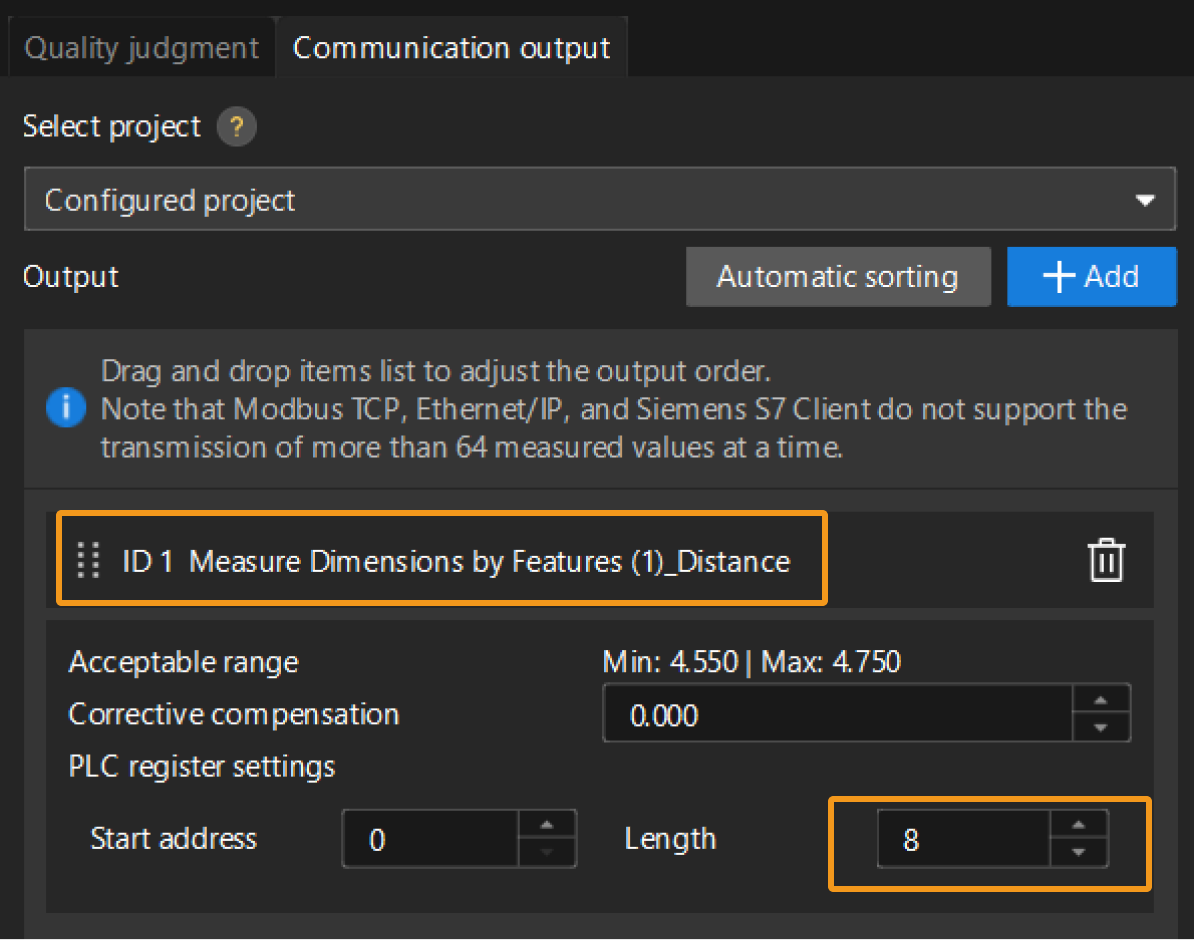
If you need to send the measurement and inspection results to an external device, you can configure the settings under the Communication output tab in the Output Management window.
|
Select the item “Distance” corresponding to pin height, and set the data length to 8 (8 values for 8 pins). |
|
Up to now, you have finished the deployment of the connector pin inspection (height & position) solution.
