Locate Feature Point of Mask

You are currently viewing the documentation for the latest version (2.2.0). To access a different version, click the "Switch version" button located in the upper-right corner of the page.

■ If you are not sure which version of the product you are currently using, please feel free to contact Mech-Mind Technical Support.

Description

This Step is used to locate a feature point within the mask.

Usage Scenario

This Step is commonly used to quickly obtain representative center points of target regions in mask images, mainly for dimension measurement scenarios.

Workflow

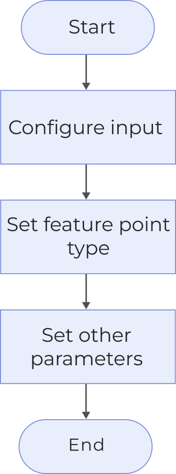
The process of configuring this Step is shown below:

locate feature point of mask process
  1. Configure the input. Connect the ports manually or select the input(s) under Input in the parameter configuration panel.

  2. In the Parameters panel, select the desired Feature Point Type.

  3. If additional parameters are available in the Parameters panel, select and adjust them as needed.

  4. Under Output, select the desired output items . Click ▶ on the left of an output item to expand it, and configure the Upper Limit and Lower Limit values to define the acceptable range.

  5. Run the Step and view output.

Input Description

The input of this Step is a mask image for locating a feature point.

Parameter Description

Parameter Description

Feature Point Type

Select the feature point type.

  • Centroid: Uses all pixel coordinates within the mask area as the feature point, representing the geometric center of the area. Applicable for scenarios where the target areas are intact and evenly distributed.

  • Bounding rectangle center: Uses the center point of the horizontal bounding rectangle that encloses the mask area as the feature point. Applicable for scenarios where the target objects are approximately rectangular with no significant rotation.

  • Minimum bounding rectangle center: Take the center point of the minimum-area rotated rectangle that completely encloses the mask area as the feature point. Applicable for scenarios where the target is rotated or tilted.

Output Description

Select the output item(s) to add the output port(s) to the Step, which outputs the specific data when the Step runs. Select the desired output items based on the measurement requirements.

If you select an expandable output item, you should expand it by clicking ▶, and then set the Upper Limit and Lower Limit values to determine the acceptable range. If the output value falls within the acceptable range, the measurement item is judged as passing (OK), or else it is judged as failing (NG).

Output item Description

Feature point

Located feature point.

Point X

X coordinate of the feature point.

Point Y

Y coordinate of the feature point.

Troubleshooting

  • For common errors, see Error Code List.

  • If the error code is inconsistent with the error message, please contact Technical Support for help.

CV-W6801

Error: The mask image is empty.

Solution: Check whether the upstream step or input port provides valid mask image data.

CV-W6802

Error: The mask image is too small.

Solution: Ensure that its width and height must be greater than or equal to 3 pixels.

CV-W6803

Error: The input mask image is not a single-channel image (CV_8UC1).

Solution: Provide a valid single-channel mask image as input.

CV-W6804

Error: The feature point type value is invalid.

Solution: Select a valid option from the drop-down list.

CV-W6805

Error: No mask detected.

Solution: Check the input mask image.

CV-W6806

Error: An internal error occurred.

Solution: Please contact Technical Support.

Is this page helpful?

You can give a feedback in any of the following ways:

We Value Your Privacy

We use cookies to provide you with the best possible experience on our website. By continuing to use the site, you acknowledge that you agree to the use of cookies. If you decline, a single cookie will be used to ensure you're not tracked or remembered when you visit this website.