Tilt Calibration (Manual)
Overview
Tilt calibration (manual) is a method for compensating for data distortion caused by sensor head mounting tilt by manually measuring and entering the sensor head tilt angle. When calibration cannot be completed automatically, such as when a calibration target is unavailable or site conditions are limited, this method can be used for quick correction. Its core is to use a precision instrument, such as an electronic level, to directly measure the sensor head tilt angles about the X, Y, and Z axes, and manually enter these angle values into the system. The system then performs geometric correction on the measurement data based on these values to eliminate profile distortion and dimensional errors.
Tilt calibration (manual) is usually used in the following scenarios:
-
After on-site installation, the system needs to be put into operation quickly, and automatic calibration cannot be performed.
-
Regularly check or verify the installation angle.
-
It is used to supplement or validate the automatic calibration results.
| The laser profiler calibration feature becomes available after a solution is opened, and the calibration results apply to all projects under that solution. |
Start the Feature
You can use the following method to enter the Tilt Calibration (Manual) window:
-
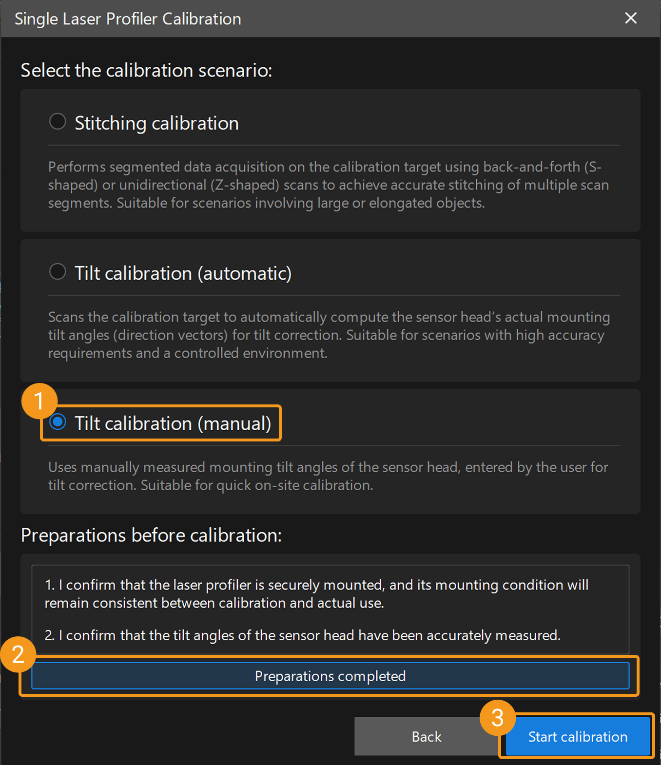
On the Mech-MSR main interface, click the Laser Profiler Calibration button on the toolbar to open the laser profiler calibration window. After selecting Single, the Single Laser Profiler Calibration window opens, where you can select the Tilt calibration (manual) scenario.
-
Select in the menu bar to open the Laser Profiler Calibration window. After selecting Single, the Single Laser Profiler Calibration window opens, where you can select the Tilt calibration (manual) scenario.
Calibration Procedure
Preparation
Before starting the calibration, ensure that the following preparations have been completed:
-
Confirm that the laser profiler is securely mounted and its mounting condition remains consistent during calibration and actual use.
-
Prepare high-precision measuring tools, such as an electronic level or angle gauge, to accurately measure the tilt angle of the sensor head.
-
Ensure that the Mech-MSR can be connected to the laser profiler normally.
 Connect to Laser Profiler
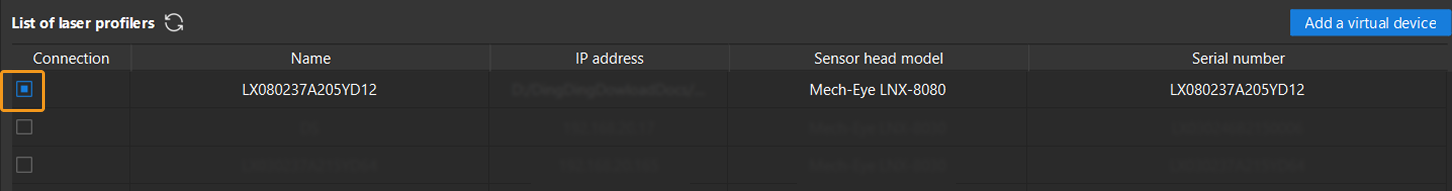
You can select laser profilers in the Connection column to connect to the devices.
|
 Measure Mounting Tilt Angle
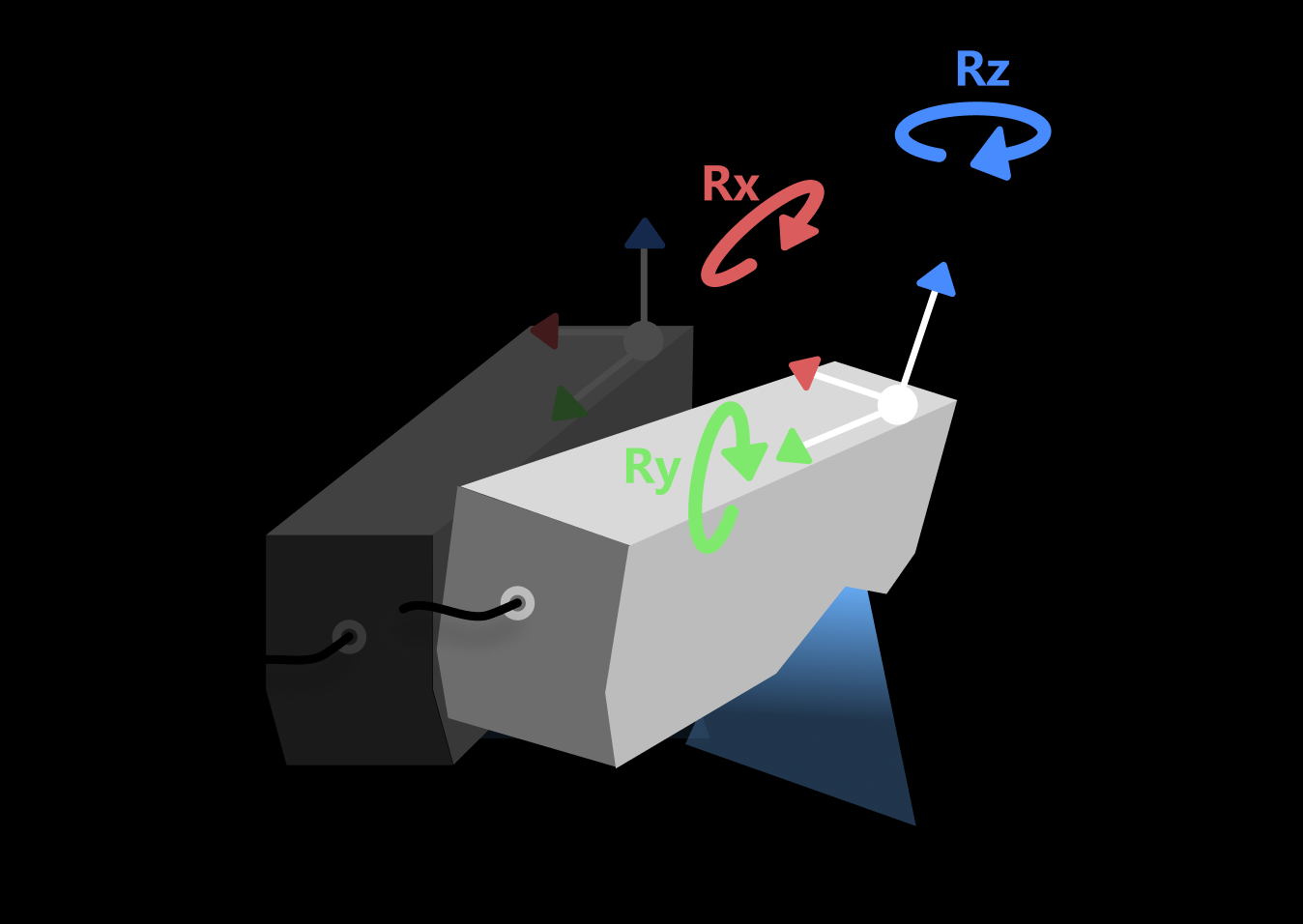
Use calibrated precision tools to measure the sensor head tilt angles about the X, Y, and Z axes, respectively.
The tilt angle refers to the angle between the actual mounting direction of the sensor head and the ideal direction. Ideally, the sensor head should be mounted perpendicular to the target object, and its scanning direction (Y-axis) should be exactly parallel to the relative motion direction of the target object.
|
After measuring the angle, click the Next button to open the Measure Mounting Tilt Angle page.
 Input Angle Value and Save It
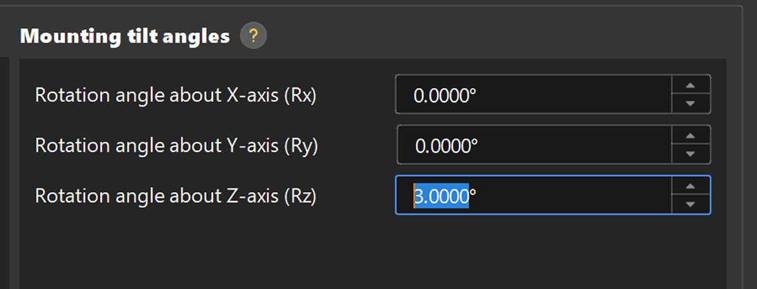
In the Measure mounting tilt window, enter the three measured angle values into the corresponding input boxes for the X, Y, and Z axes. After confirming that the calibration result is correct, click the Save. In the pop-up window that appears, specify the file name and storage path to save the calibration result and complete the calibration.
| After calibration is complete, it is recommended to keep the device installation unchanged under the same conditions. Otherwise, recalibration is required. |
 Validate Calibration (Optional)
To verify the calibration, scan a reference object of known dimensions, such as a calibration block, and check whether the measurement results match the expected values. If any deviation is found, check whether the angle measurements are accurate and recalibrate if necessary.
Apply Calibration Result
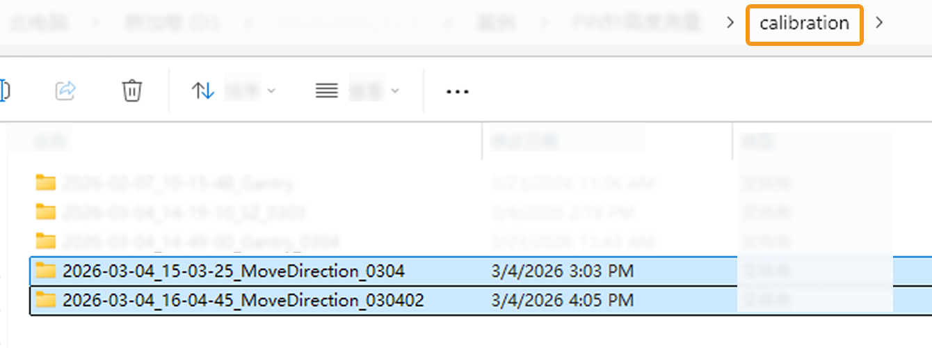
Tilt calibration (manual) results are saved in the calibration folder under the solution folder and can be used by the 3D Laser Profiler Step in any project in the current solution.
The procedure is as follows:
-
In the parameter configuration panel of the Step, change the Camera Mode to One.
-
Select the Tilt Correction parameter. The Select Calibration Result parameter is then displayed in the parameter panel. Choose the calibration result to use from the drop-down menu.
-
After configuring the other parameters of this Step, run the Step to apply the selected calibration result.