Stitching Calibration
Overview
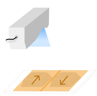
Stitching calibration is a high-precision data acquisition and processing technique for measuring large-sized or elongated objects. This method acquires segmented data from the calibration target and solves for the relative poses between the data segments to achieve accurate global stitching of the multi-segment data.
-
Calibration procedure
When establishing the calibration parameters, a unidirectional (Z-shaped) scanning strategy must be used. Regardless of the path used in subsequent applications, the two data acquisitions during calibration must follow exactly the same scanning direction to ensure the accuracy of the coordinate transformation.
-
Actual application
In actual measurement, you can flexibly choose either a bidirectional (S-shaped) or unidirectional (Z-shaped) scanning strategy as needed. Based on the calibration results, the system automatically identifies the scanning direction and applies the appropriate coordinate transformation strategy, such as mirror correction, to ensure that multiple data segments are seamlessly stitched into highly complete surface data.
|
|
S-shaped scanning |
Z-shaped scanning |

Start the Feature
You can open the calibration window in the following ways:
-
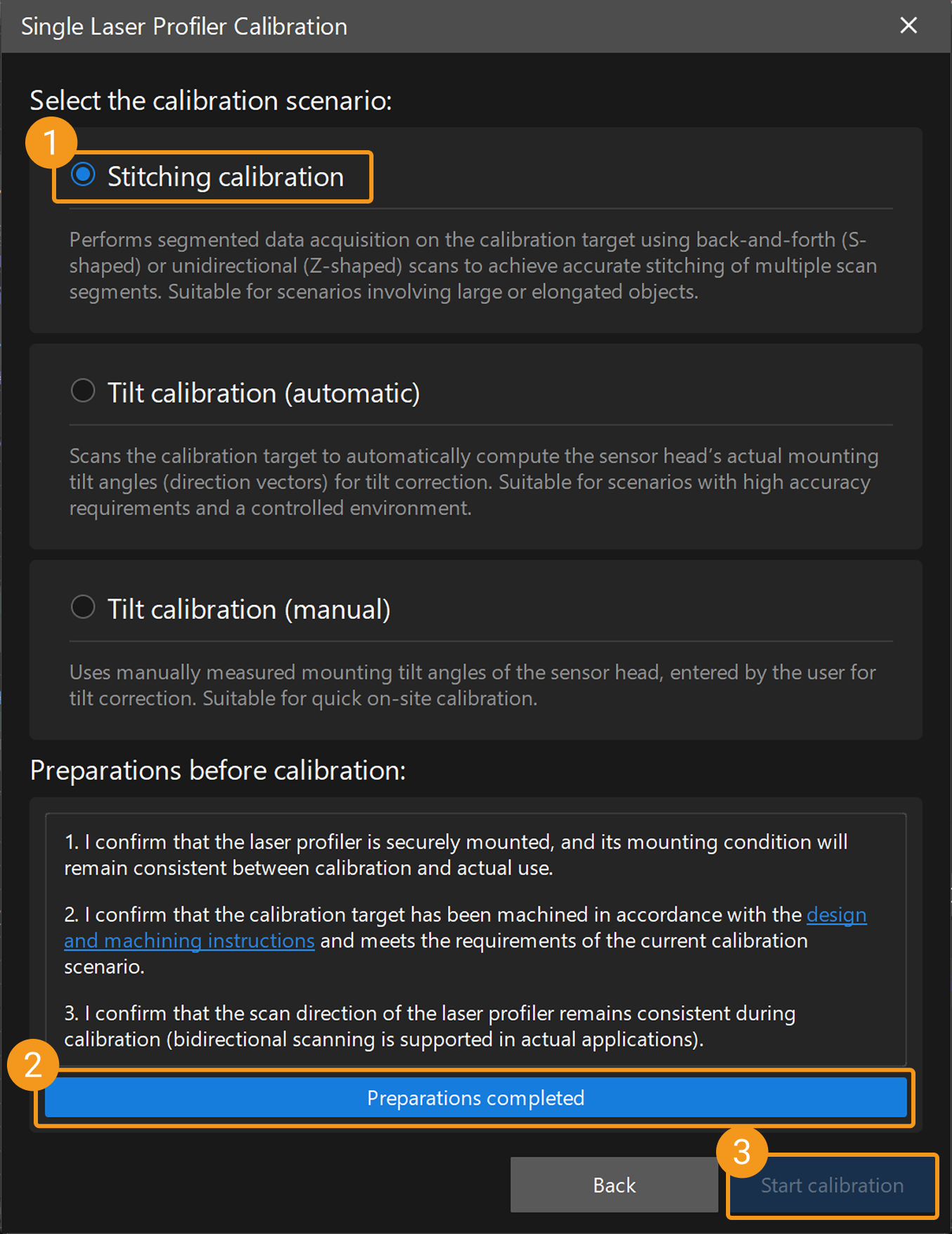
In the home interface of Mech-MSR, click the Laser Profiler Calibration button in the toolbar to open the calibration window. After selecting Single, the Single Laser Profiler Calibration window opens, where you can select the Stitching calibration scenario.
-
Select in the menu bar to open the Laser Profiler Calibration window. After selecting Single, the Single Laser Profiler Calibration window opens, where you can select the Stitching calibration scenario.
| The laser profiler calibration feature is available after a solution is opened, and the calibration results apply to all projects in that solution. |
Calibration Procedure
Preparation
Before starting the calibration, ensure that the following preparations have been completed:
-
Confirm that the laser profiler is securely mounted and its mounting condition remains consistent during calibration and actual use.
-
Confirm that a double-frustum calibration target that meets the requirements of the current application has been manufactured in accordance with calibration target design and machining instructions, and ensure that the calibration target placement meets the requirements.
-
Confirm that the scanning direction of the laser profiler remains exactly the same throughout calibration (alternating forward and reverse scanning is supported in actual applications).
-
Ensure that the Mech-Eye Viewer and Mech-MSR can connect to the laser profiler normally.
-
In the Mech-Eye Viewer software, adjust the parameters to ensure that the acquired image data has no obvious missing regions and contains minimal noise, and save the parameter group as the configuration parameter group for the laser profiler during calibration.
-
To ensure calibration accuracy, warm up the laser profiler before calibration by continuously acquiring data for more than one hour after power-on under the actual operating parameters.
Instructions
 Connect to Laser Profiler
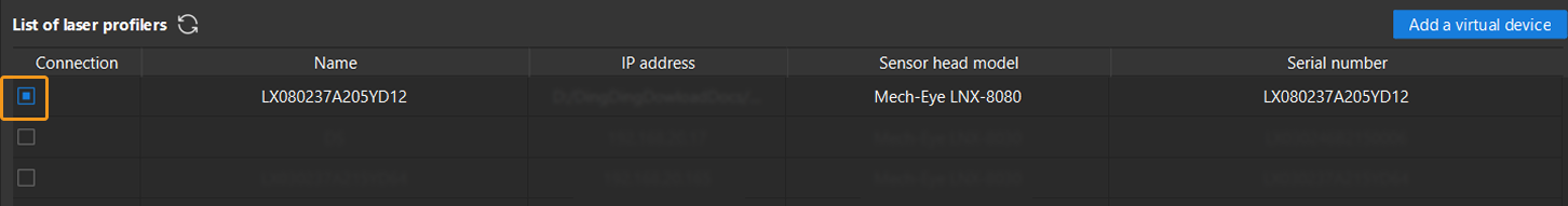
You can select the laser profiler in the Connection column to connect to the device.
|
After connecting the laser profiler, click the Next button to go to the Axis Direction Mapping settings page.
 Set Axis Direction Mapping
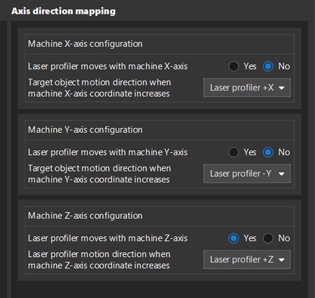
Axis direction mapping is used to establish an accurate correspondence between the machine coordinate system and the coordinate system of the surface data acquired by the laser profiler. Based on the actual installation, configure the direction mapping between the machine axes and the laser profiler axes to ensure accurate correspondence between the machine coordinate system and the surface data coordinate system, and to avoid data errors or stitching failures caused by coordinate system misalignment.
| The following configuration procedure is based on a typical application example (see the figure). The actual configuration parameters must be determined strictly according to the installation layout of the on-site equipment. |
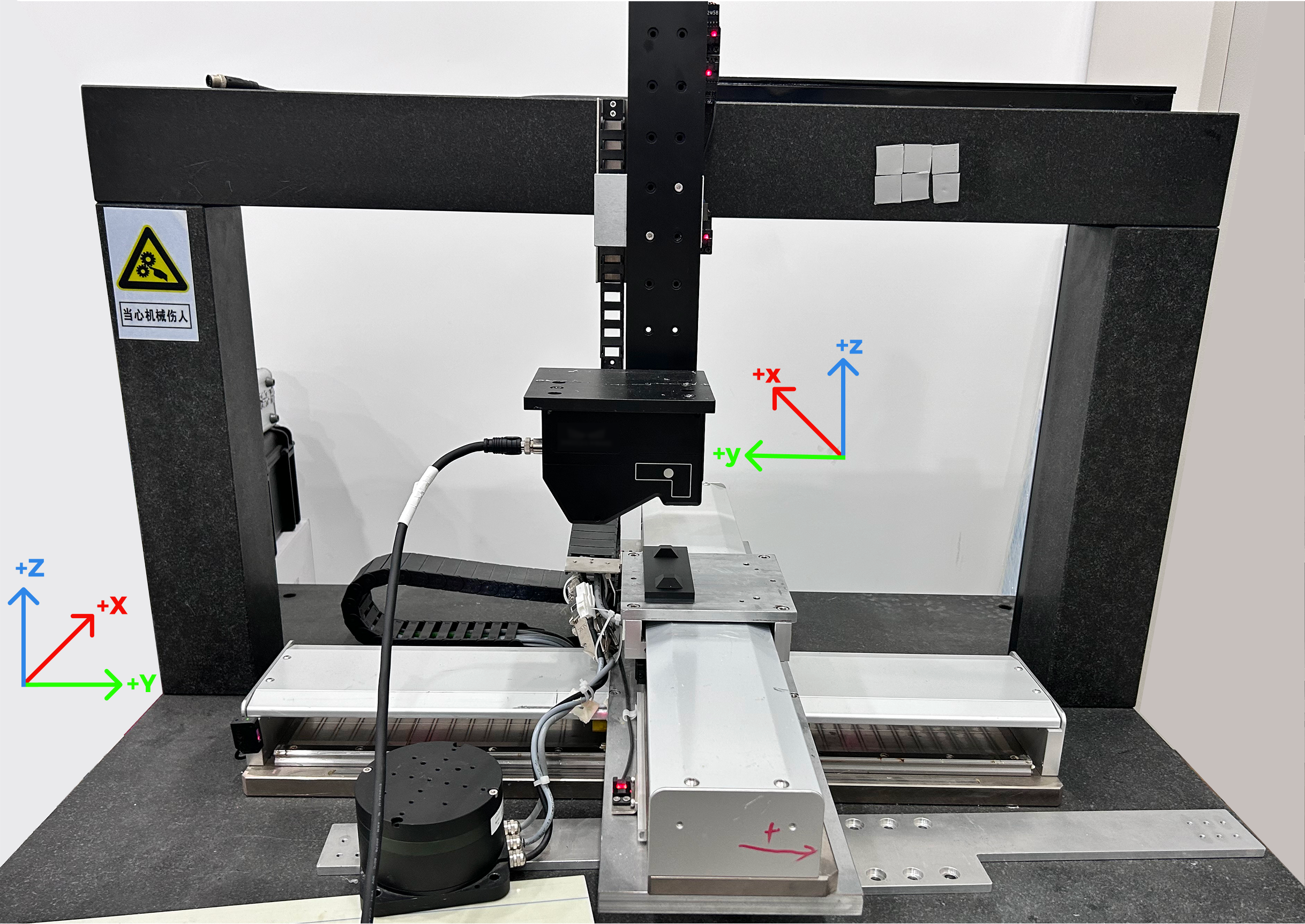
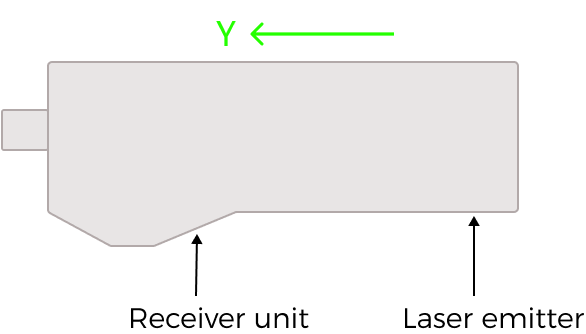
The Y-axis direction of the laser profiler is fixed as the direction from the laser emitter to the photosensitive unit in the sensor head. The directions of the other axes can be determined according to the right-hand coordinate system: the right thumb points in the positive X-axis direction, the index finger points in the positive Y-axis direction, and the middle finger points in the positive Z-axis direction.
Follow the steps below:
-
Confirm the motion relationship between laser profiler and machine axis.
-
Determine which machine axis or axes the laser profiler sensor head moves with, and how the motion directions correspond.
-
In the software configuration interface, locate the corresponding settings for each machine axis (X, Y, Z), and select Yes or No as appropriate.
-
For each machine axis set to Yes, observe along which axis and in which direction the laser profiler moves when the coordinate value of that machine axis increases.
-
-
Confirm the motion direction of the target object relative to the laser profiler.
After determining the motion relationship of the laser profiler itself, you also need to determine how the target object moves relative to the laser profiler:
-
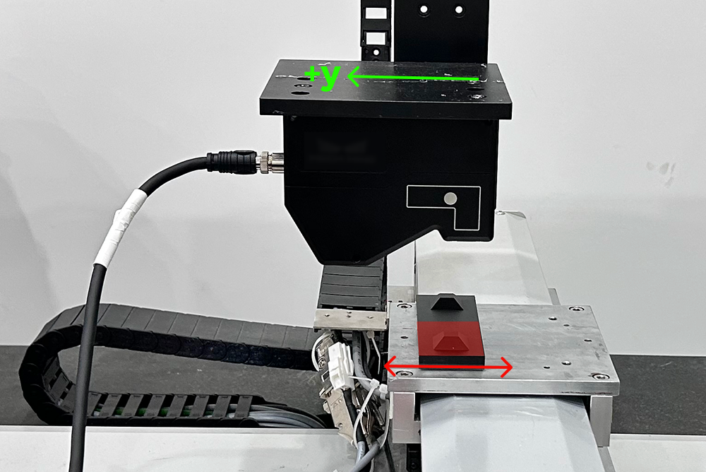
Each acquisition: During each data acquisition (i.e., each scan of one frustum), either the machine moves the calibration block along one of its axes, or one of the machine axes moves the laser profiler along its own Y-axis, thereby completing the data acquisition of the current frustum.
-
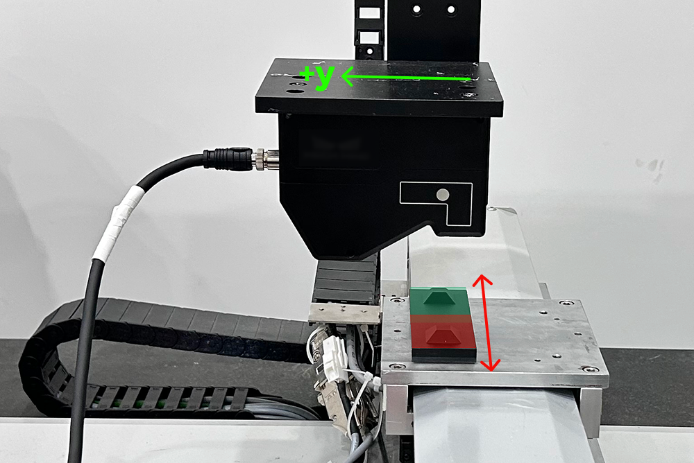
Inter-acquisition: In order to acquire data from the two frustums separately, either the machine carries the calibration block along another machine axis, or another machine axis moves the laser profiler to a position directly above the other frustum, thereby completing the position switch between the two acquisitions.
- Example description
-
In the example, the laser profiler sensor head is rigidly mounted on the machine’s Z-axis and can move up and down with the Z-axis. Therefore, under Machine Z-axis configuration, set the Laser profiler moves with machine Z-axis to Yes, set the corresponding item under machine X-axis and Y-axis configuration to No, and set the Laser profiler motion direction (when the Machine Z-axis coordinate increases) to Laser profiler +Z.
The calibration target moves along the machine’s X- and Y-axes, allowing the laser profiler to scan the two frustums on the calibration target separately and complete two data acquisitions. During each round of data acquisition, the robot moves along the Y-axis with the calibration block; for two rounds of data acquisition, the robot also moves along the X-axis with the calibration block to switch positions between rounds of data acquisition.
-
After the data acquisition is completed, click the Next button to go to the calibration target settings page.
 Calibration Target Settings
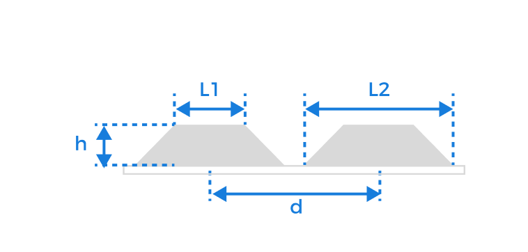
The stitching calibration uses the target with two frustums. Enter the parameter values according to the actual design and machining of the calibration target.
| Be sure to enter accurate parameter values. |
Parameter |
Description |
Upper base length (L1) |
The side length of the frustum’s smaller base, in millimeters (mm). |
Lower base length (L2) |
The side length of the frustum’s larger base, in millimeters (mm). |
Frustum height (h) |
The vertical distance from the upper base to the lower base of the frustum, in millimeters (mm). |
Translation distance (d) |
The distance between the centerlines of neighboring frustums, in millimeters (mm). |
After entering the accurate parameter values and confirming that they are correct, click the Next button to go to the calibration page.
 Compute Calibration
Follow the steps below to complete calibration:
-
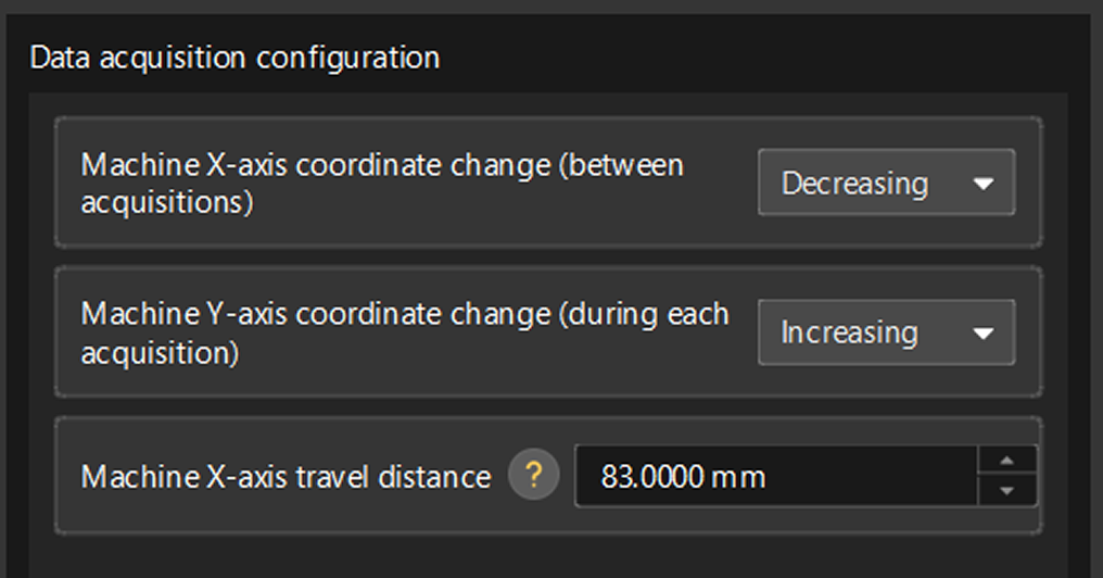
Complete data acquisition configuration.
Parameter Description Machine X/Y/Z-axis coordinate change (between acquisitions)
The system will automatically determine the corresponding machine axis based on the previous settings.
In this case, observe whether the coordinate value of the corresponding machine axis increases or decreases between the first and second data acquisitions, so as to determine the motion direction of the calibration block relative to the laser profiler.
Machine X/Y/Z-axis coordinate change (during each acquisition)
The system will automatically determine the corresponding machine axis based on the previous settings.
At this time, observe whether the coordinate value of the corresponding machine axis increases or decreases during each data acquisition, so as to determine the scanning direction of the laser profiler.
Configuration parameter group
The parameter group used by the laser profiler for data acquisition.
Machine X/Y/Z-axis travel distance
The distance traveled by the corresponding machine axis between two data acquisitions (i.e., the displacement required to move from one frustum to the other).
By default, this value is the same as the Translation distance parameter value of the calibration target.
- Example description
-
In the example, Machine X-axis coordinate change (between acquisitions) is set to Decreasing, and Machine Y-axis coordinate change (during each acquisition) is set to Increasing. Since the Translation distance of the calibration target is 83 mm, the Machine X-axis travel distance remains 83 mm.
-
Acquire data.
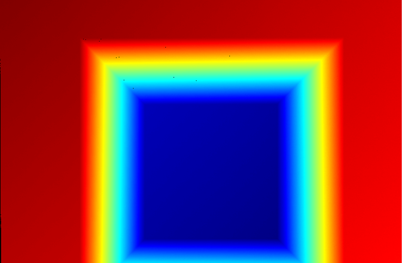
Complete two data acquisitions separately. The acquired data should meet the following requirements:
-
The calibration target should be located at the image center.
-
The image should contain only the six feature surfaces of the calibration target, and each surface should be fully captured.
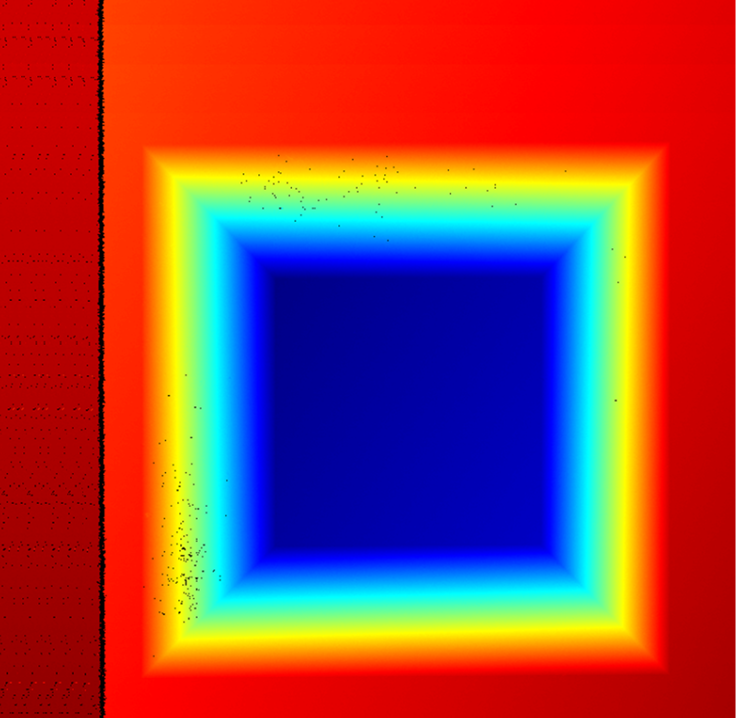
If other surface data exists, enable Use feature region and adjust its size and position to ensure that the region contains only the six feature surfaces of the calibration target. -
The frustum on the calibration target should face the sensor head as directly as possible and should not be rotated about the X-, Y-, or Z-axis.
-
The image should have minimal noise.
Normal Severe point loss Incomplete surface Extra surface present Excessive noise 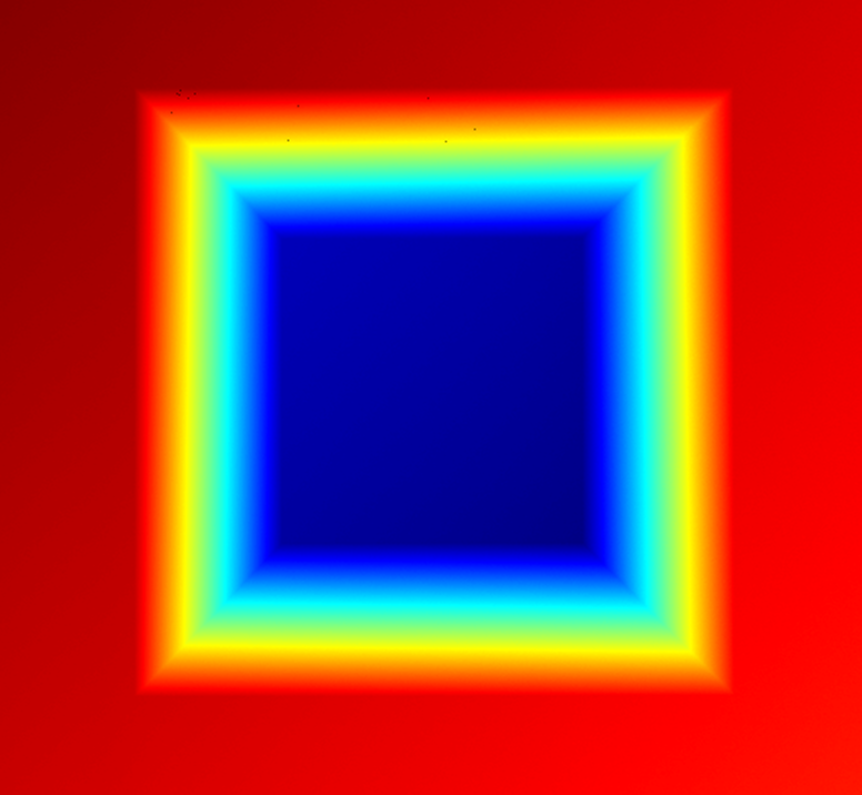
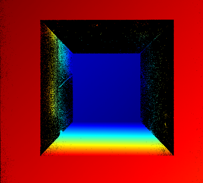
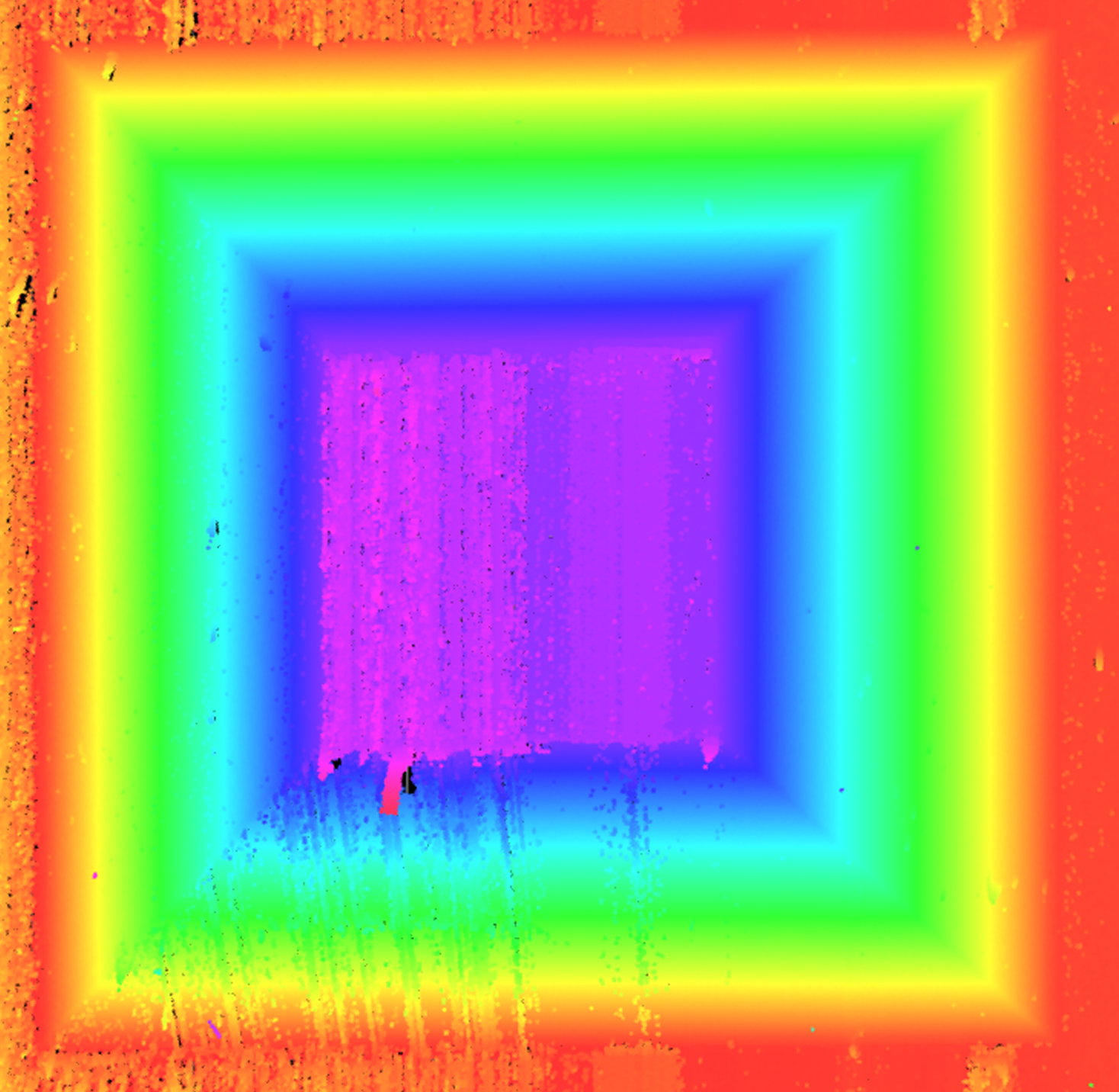
If the quality of the acquired data does not meet the requirements, readjust the parameters in the Mech-Eye Viewer software until the image quality meets the requirements, and then save the parameter group. Then return to step 1 and re-select the Configuration parameter group.
After data acquisition is complete, click Next to start the calibration calculation.
-
-
Compute calibration.
Click the Start calibration button to start calibration. The system will automatically analyze the geometric relationship between the two scans, calculate the actual mounting tilt angle (direction vector) of the sensor head, and generate the calibration result.
When the FOVs from laser profilers in the two data acquisitions overlap, enable Fuse images to see whether the fused image meets expectations. 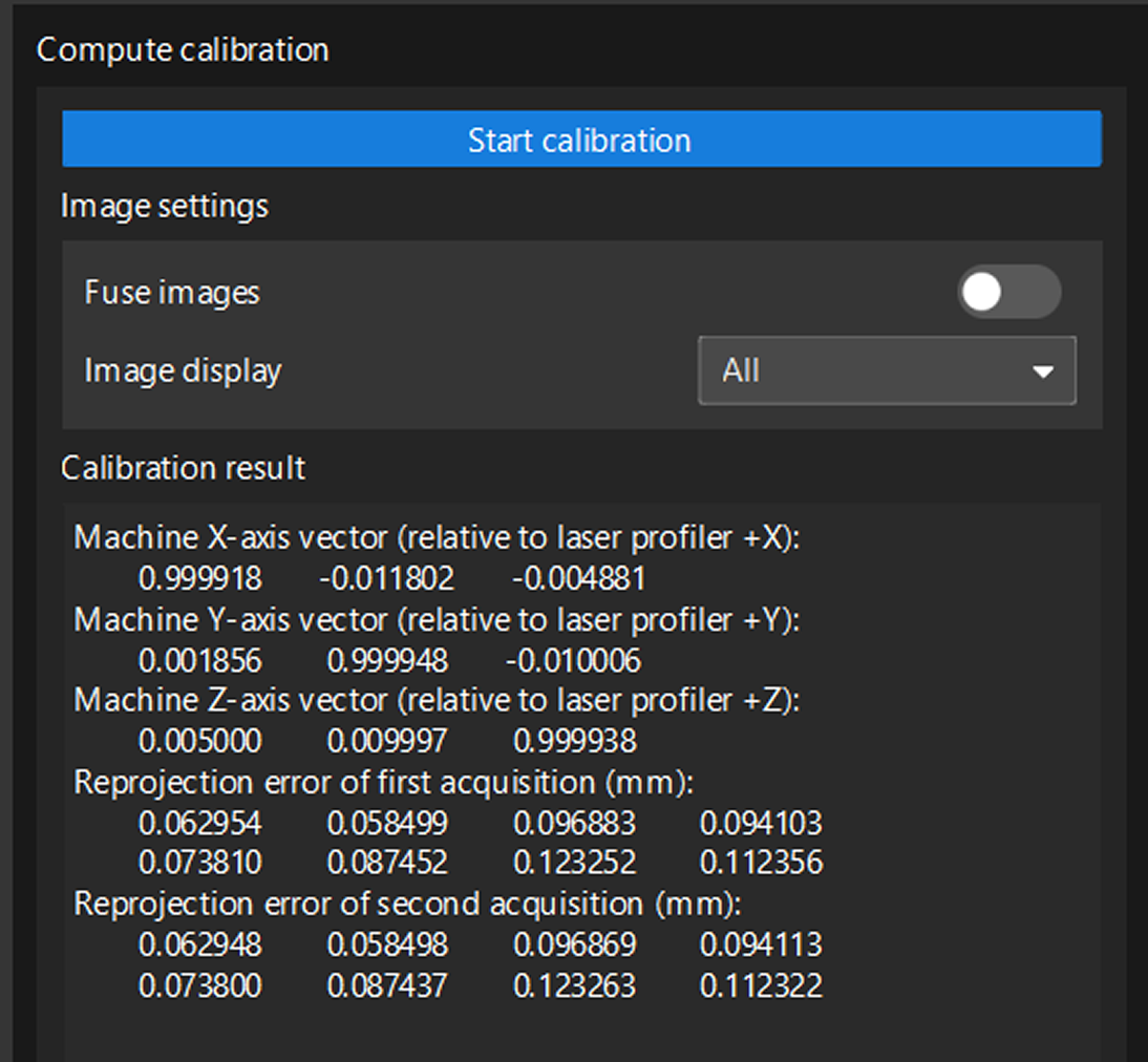
-
Check the calibration result to ensure that the calibration accuracy meets the requirements.
After confirming that the calibration result is correct, click the Save. In the pop-up window that appears, specify the file name and storage path to save the calibration result and complete the calibration.
Apply Calibration Result
The stitching calibration results are saved in the calibration folder under the solution folder and can be used by the 3D Laser Profiler Step in any project in the current solution.
The procedures are as follows:
-
In the parameter configuration panel of the Step, change the Camera Mode to One.
-
Select the S/Z Scan Stitching parameter. The Select Calibration Result parameter will then appear in the parameter panel. Choose the calibration result to use from the drop-down list.
-
Under Scan Segment Settings, click the Open the editor button to configure multiple scan segments.
-
After configuring other parameters for this Step, you can run the Step to apply the selected calibration results.
Appendix: Information about Calibration Results
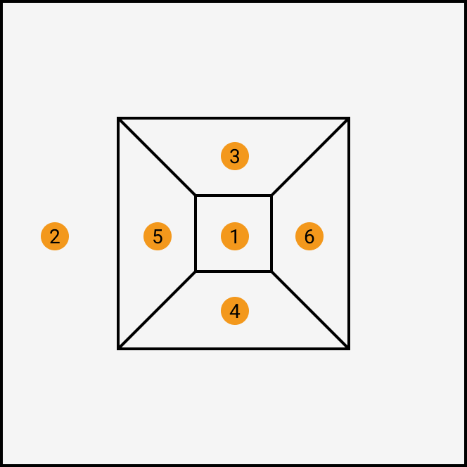
In the data acquired by each laser profiler, the points and planes are indexed as shown in the figure below (top view). P1 to P8 are eight corners of a frustum, and ① to ⑥ represent the six planes that should be included in the data acquired by each laser profiler.
|
|
Points |
Planes |

When stitching images, data from multiple acquisitions must be transformed into the coordinate system of the data from the first acquisition.
-
Machine axis vectors (relative to the corresponding axes of the laser profiler)
Configure this parameter according to the actual setup, based on the correspondence between the machine axes and the coordinate axes of the laser profiler. In general, each pair of corresponding axes should be perfectly parallel to ensure accurate calibration and measurement.
-
Reprojection error
The reprojection error is generated by calculating the coordinate deviations of the frustum’s eight corners from reference coordinates, measured in millimeters. A smaller reprojection error value indicates better calibration accuracy.