Detect and Fit Oblong Hole
Description
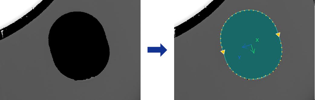
This Step is used to fit an oblong hole to the oblong-hole-shaped edge detected from the image.
Usage Scenario
This step is primarily used for precise measurement of parts, workpieces, or assemblies containing oblong holes, and is common in automotive, machining, and assembly inspection applications.
Basic Concepts
-
Oblong hole
A hole structure consisting of a rectangular midsection with semicircular ends, widely used in mechanical and automotive parts to allow for sliding or adjustment.
-
Caliper
In image processing, a virtual measurement tool detects edges within a specified region. Adjusting its count, width, and length affects the accuracy and stability of edge detection.
-
Edge Polarity
It refers to the direction of grayscale change across an edge, e.g., dark-to-light or light-to-dark.
Workflow
The process of configuring this Step is shown below:

-
Configure the input. Connect the Step ports in the graphical programming workspace or select the input under Input in the parameter configuration panel.
-
Complete the ROI Settings.
-
Set other parameters.
-
Confirm the output items in the Output section.
-
Run the Step, and view output.
Input Description
| Input Item | Description |
|---|---|
Image |
The image used for detecting an oblong-hole-shaped edge. |
Alignment Parameter Group |
This Step is used to adjust the pose of the ROI synchronously according to the pose transformation of the target object. |
Parameter Description
| Parameter | Description |
|---|---|
ROI Settings |
You can draw an oblong hole ROI, and the system will extract multiple columns of pixels according to the caliper settings. The detected edge points in each column will be used for oblong hole fitting. For a closed ROI, such as an oblong hole, the calipers detect edges outward from the inside of the ROI. The caliper direction generally does not need adjustment, and rotating the ROI does not change the detection direction. See 2D ROI Settings to learn more about ROI and calipers. |
Edge Polarity |
This parameter specifies the direction in which the grayscale values change at the edges. Value list:
|
Filter Window Size |
Specify the window size to be used when filtering each column of pixels in its direction. Filtering can reduce noise and improve the stability of edge detection results. |
Edge Type |
Define the edge types to be retained in edge detection. Value list: Best, First, Last. |
Gray Value Change Threshold |
This parameter specifies the minimum gray value change between adjacent pixels at the edge of an extracted pixel column required for edge point detection. Setting this parameter value properly can effectively filter out weak edges and noise. |
Use Relative Threshold |
Once selected, an edge point is detected only if the gray value change between adjacent pixels at the edge of a pixel column meets or exceeds the specified percentage of the maximum change in that column. Once this parameter is selected, set Relative Threshold. |
Outlier Fraction |
The percentage of outlier points to be removed during oblong hole fitting. |
Output Description
Select the output item(s) to add the output port(s) to the Step, and the corresponding data will be output after the Step is run. You can select the output according to the actual measurement requirements.
| If you select an expandable output item, you must expand it by clicking ▶, and then set the Lower Limit and Upper Limit values to determine the acceptable range. If the output value falls within the acceptable range, the measurement item is judged as OK; otherwise, it is judged as NG. |
| Output Item | Description |
|---|---|
Oblong Hole Pose |
The position and orientation of the fitted oblong hole. |
Center Point |
The geometric center of the fitted oblong hole. |
Center X |
The X coordinate of the center point of the fitted oblong hole. |
Center Y |
The Y coordinate of the center point of the fitted oblong hole. |
Minor Axis Length |
The fitted oblong hole width, which is the diameters of the semicircles at both ends of the oblong hole. |
Major Axis Length |
The total length of the fitted oblong hole is equal to the distance between the centers of the semicircles at the ends of the oblong hole (i.e., the length of the middle rectangle) plus the radii of the two semicircles. |
Oblong Hole Rotation Angle |
The rotation angle of the fitted oblong hole, relative to the positive X-axis direction. |
Fitted Oblong Hole |
The fitted oblong hole. |
Troubleshooting
|
For common errors, see Error Code List. |