Create Point (2D)
Usage Scenario
This Step is commonly used to generate feature points for measurement assistance or as fundamental data for subsequent geometric calculations.
Workflow
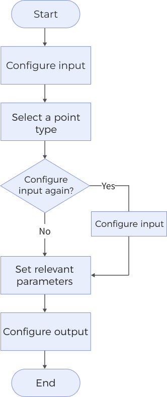
The process of configuring this Step is shown below:
-
Configure the input. Connect the ports manually in the graphical programming workspace or select the input under Input in the parameter configuration panel.
-
In the Parameters section, select the Point Type to determine how a point is generated, and choose the corresponding input data in the Input section.
-
If there are additional parameters in the Parameters section, select and adjust them according to your actual needs.
-
Select the desired output items under Output. For an expandable output item, click ▶ and configure the Min and Max values to determine the acceptable range for the item.
Parameter Description
Point Type
The method to create a point.
For different types of points, the geometric features input into the Step and the parameters that need to be adjusted will vary accordingly. The specific correspondences are as follows:
| Point Type | Geometric Features to be Input | Parameter Adjustment |
|---|---|---|
Constant Point (Custom) |
- |
You need to set the X and Y coordinates of the constant point in the Parameters section. After the Step is run, the constant point will be output. |
Intersection of Two Lines |
Line 1, Line 2 |
After the Step is run, it outputs the intersection point of the two lines. |
Projected Point on Line |
Line, Point |
After the Step is run, it outputs the projection of the point onto the line. No other parameters need to be adjusted. |
Given Point |
Point |
After the Step is run, it outputs the given point. No other parameters need to be adjusted. |
Constant Point (Step input) |
Point X, Point Y |
After the Step is run, it outputs the constant point. No other parameters need to be adjusted. |
Output Description
Select the output item(s) to add the output port(s) to the Step, and the corresponding data will be output after the Step is run. You can select the output according to the actual measurement requirements.
|
If you select an expandable output item, you should expand it by clicking ▶, and then set the Min and Max values to determine the acceptable range. If the output value falls within the acceptable range, the measurement item is judged as passing (OK), or else it is judged as failing (NG). |
| Output item | Description |
|---|---|
Point X |
X coordinate of the created point. |
Point Y |
Y coordinate of the created point. |
Included Angle |
The angle between two lines. |
Created Point |
The point created on the basis of the selected point type, which can be used as an input for other steps. |
Troubleshooting
|