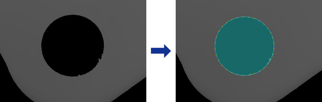
Detect and Fit Circle
Usage Scenario
This Step is mainly used for automatic inspection, center localization, radius measurement of workpieces or parts with circular contours.
Basic Concepts
-
Caliper
In image processing, a virtual measurement tool detects edges within a specified region. Adjusting its count, width, and length affects the accuracy and stability of edge detection.
-
Edge Polarity
It refers to the direction of grayscale change across an edge, e.g., dark-to-light or light-to-dark.
Workflow
The process of configuring this Step is shown below:

-
Configure the input. Connect the Step ports in the graphical programming workspace or select the input under Input in the parameter configuration panel.
-
Complete the ROI Settings.
-
Set other parameters.
-
Confirm the output items in the Output section.
-
Run the Step, and view output.
Input Description
| Input Item | Description |
|---|---|
Image |
Image used to detect circular edges. |
Alignment Parameter Group |
This Step is used to adjust the pose of the ROI synchronously according to the pose transformation of the target object. |
Parameter Description
| Parameter | Description |
|---|---|
ROI Settings |
A circular ROI can be drawn. The system then extracts multiple pixel columns based on the caliper settings, and edge points detected in each column are used for circle fitting. For a closed ROI, such as a circle, the calipers detect edges outward from the inside of the ROI. The caliper direction generally does not need adjustment, and rotating the ROI does not change the detection direction. See 2D ROI Settings to learn more about ROI and calipers. |
Edge Polarity |
This parameter specifies the direction in which the grayscale values change at the edges. Value list:
|
Filter Window Size |
Specify the window size to be used when filtering each column of pixels in its direction. Filtering can reduce noise and improve the stability of edge detection results. |
Edge Type |
Define the edge types to be retained in edge detection. Value list: Best, First, Last. |
Gray Value Change Threshold |
This parameter specifies the minimum gray value change between adjacent pixels at the edge of an extracted pixel column required for edge point detection. Setting this parameter value properly can effectively filter out weak edges and noise. |
Use Relative Threshold |
Once selected, an edge point is detected only if the gray value change between adjacent pixels at the edge of a pixel column meets or exceeds the specified percentage of the maximum change in that column. Once this parameter is selected, set Relative Threshold. |
Outlier Fraction |
The percentage of outlier points to be removed during circle fitting. |
Output Description
Select the output item(s) to add the output port(s) to the Step, and the corresponding data will be output after the Step is run. You can select the output according to the actual measurement requirements.
| If you select an expandable output item, you must expand it by clicking ▶, and then set the Lower Limit and Upper Limit values to determine the acceptable range. If the output value falls within the acceptable range, the measurement item is judged as OK; otherwise, it is judged as NG. |
| Output Item | Description |
|---|---|
Fitted Circle |
The circle obtained through fitting. |
Circle Center |
The center of the fitted circle. |
Circle Center X |
The X coordinate of the center of the fitted circle. |
Circle Center Y |
The Y coordinate of the center of the fitted circle. |
Radius |
The radius of the fitted circle. |
Troubleshooting
|
CV-W8801
Error: Invalid ROI settings.
Possible cause: The size of the ROI is too large, more than twice the size of the image.
Solution: Reset the ROI to ensure that it is of a proper size.
CV-W8802
Error: The set “Start Angle” value is outside of the valid range.
Solution: Ensure the parameter value is within the range of -180° to 180°.
CV-W8803
Error: The set “Angle Span” value is outside of the valid range.
Solution: Ensure the parameter value is within the range of 0° to 360°.
CV-W8804
Error: The set “Caliper Count” value is outside of the valid range.
Solution: Ensure the parameter value is within the range of 0–10000.
CV-W8805
Error: The set “Caliper Length” value is outside of the valid range.
Solution: Ensure the parameter value is within the range of 0–10000.
CV-W8806
Error: The set “Caliper Width” value is outside of the valid range.
Solution: Ensure the parameter value is within the range of 0 to 100.
CV-W8807
Error: The set “Filter Window Size” value is outside of the valid range.
Solution: Ensure the parameter value is within the range of 0 to 100.
CV-W8808
Error: The set “Edge Polarity” is invalid.
Solution: Select valid edge polarity from the drop-down list.
CV-W8809
Error: The set “Edge Type” is invalid.
Solution: Select a valid edge type from the drop-down list.
CV-W8810
Error: The set “Gray Value Change Threshold” value is outside of the valid range.
Solution: Ensure the parameter value is within the range of 0 to 255.
CV-W8811
Error: The set “Relative Threshold” value is outside of the valid range.
Solution: Ensure the parameter value is within the range of 0% to 100%.
CV-W8812
Error: The set “Outlier Fraction” value is outside of the valid range.
Solution: Ensure the parameter value is within the range of 0% to 100%.
CV-W8813
Error: Unable to fit a circle since the detected edge points are insufficient.
Possible cause:
-
Invalid ROI settings.
-
The calipers are not set properly.
-
The “Gray Value Change Threshold” and “Relative Threshold” values are too large.
-
The selected “Edge Polarity” is not set properly.
Solution:
-
Ensure that the ROI is not too small.
-
Adjust the caliper settings to ensure edge points can be detected from the calipers.
-
Lower the “Gray Value Change Threshold” and “Relative Threshold”.
-
Ensure that the “Edge Polarity” parameter is set properly.