N-Point Calibration (Gantry)
Overview
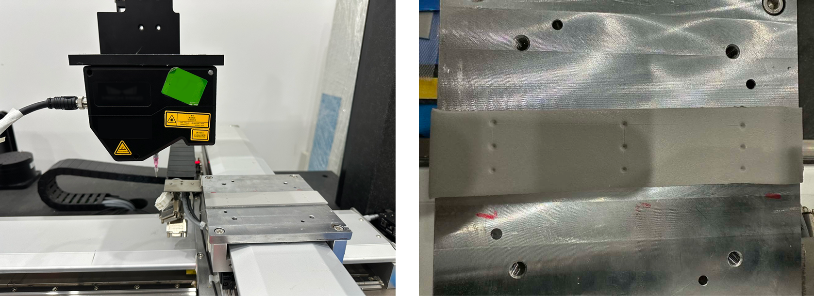
N-point calibration is a high-accuracy calibration workflow in Mech-MSR designed specifically for collaborative operation between a three-axis gantry robot and a 3D laser profiler. The core objective of this workflow is to establish an accurate mapping relationship (hand-eye calibration) between the surface data coordinate system (the surface data acquired by the laser profiler) and the machine coordinate system (defined by the motion axes of the gantry robot). By solving for the rotation matrix and translation vector between the two coordinate systems, the system can accurately transform the measured coordinates of surface feature points into the machine coordinate system.
N-point calibration is commonly used in high-precision dispensing guidance systems, where the accuracy of the dispensing trajectory depends on the accuracy of the coordinate transformation established during calibration. In addition, N-point calibration is also applicable to new energy manufacturing and can provide a coordinate reference for trajectory guidance in processes such as battery pack enclosure welding and laser welding of battery terminals.
Preparations
Basic Requirements
Before calibration, please confirm that the following basic requirements have been met:
-
Fixture requirements: The calibration fixture must be rigidly connected to the machine worktable to ensure that no displacement or vibration occurs throughout the full travel of the machine X, Y, and Z axes. The fixture surface should be kept clean and free of stains and scratches.
-
Image quality: The laser profiler must be able to image clearly in the calibration area, with clear and sharp edges of the feature holes, free from overexposure and underexposure.
-
Communication link: Communication between the machine controller and the laser profiler must be normal, point-triggered acquisition must be supported, and data transmission must be complete and lossless.
Recommended Configuration
To achieve the best calibration accuracy, it is recommended to have the following conditions. If not, the calibration process can still be executed, but the calibration accuracy may be affected in varying degrees.
| Configuration Item | Recommended Configuration | Impact on Accuracy |
|---|---|---|
Machine repeatability |
≤ ± 5 μm (consumer electronics scenarios) |
Repeatability errors will be directly added to the calibration extrinsic parameters, affecting the accuracy of the final coordinate transformation. |
Position feedback |
Encoder-based closed-loop feedback |
Fixed-rate drive control (without encoders) carries a risk of step loss, cannot compensate for mechanical transmission errors, and is prone to position drift during long-term operation. |
Feature point obtaining method |
Recommended: Conical punch + low-rebound silicone pad |
Manual operation error is minimized, the feature holes are clear and stable in shape, and repeatability is good. |
Punching operation |
Keep the needle tip or conical punch perpendicular to the pad surface, use an appropriate punching depth, and complete the punch in a single attempt |
An excessively tilted punch will deform the hole and introduce systematic deviation during feature extraction. |
Equipment warm-up |
Warm up the laser emitter of the laser profiler for ≥ 15 minutes |
Light intensity is unstable during cold start, which reduces the consistency of feature extraction. |
Environmental conditions |
Stable ambient temperature and no obvious nearby vibration sources |
Temperature fluctuations cause thermal deformation of the structure; vibrations cause point cloud data to jitter, which affects the accuracy of feature extraction. |
Comparison of Feature Point Obtaining Methods
| Method | Accuracy Level | Description |
|---|---|---|
Conical punch + silicone pad (recommended) |
High |
Use a conical punch vertically to create a clear indentation; operation is easy and repeatability is good. |
Tip-to-tip |
Medium to low |
Manual alignment of two tips introduces large subjective error, and inconsistent contact force leads to random deviation. |
Tip-to-scribed cross |
Medium |
Manual alignment to a crosshair engraved on a plane introduces visual reading error, and there is a Z-direction deviation between the plane height and the tip contact point. |
| When using the recommended method, it is recommended to use a fixed base to ensure that the silicone pad remains flat and does not shift, keep the conical punch vertical during punching, form a clear indentation in one punch, and use the laser profiler debugging tool (Mech-Eye Viewer) to preview the image and confirm that the features are distinguishable before proceeding. |
Accuracy Statement
This calibration method uses the N-point method to compute the hand-eye transformation matrix, and its accuracy depends heavily on the hardware preparation and operating practices described above.
Calibration results may deviate significantly, with errors ranging from tens to hundreds of microns, if:
-
The machine repeatability does not meet the recommended requirement.
-
A non-recommended feature point obtaining method is used (such as tip-to-tip or tip-to-scribed cross).
-
The punch is excessively tilted, causing distortion of the feature holes.
-
The fixture shifts during calibration.
Under the above conditions, the actual positioning accuracy of the system may be lower than the nominal value specified in the product datasheet.
| It is recommended to perform repeatability verification before formal calibration: carry out 2 to 3 independent calibrations on the same set of points and compare the differences among the results. If the root mean square (RMS) value of the residuals of the calibration data points or the parameters of the transformation matrix fluctuate significantly, first check whether the preparation work described in this section has been properly completed. |
Calibration Procedure
You can select the calibration fixture and the corresponding punching or touch device according to on-site conditions and requirements. This section uses a silicone-pad calibration fixture and a conical punch as an example to describe the punching, data acquisition, and data preprocessing procedures for completing N-point calibration on a gantry machine.
Select a Punching Strategy
During calibration, after the end tool is fitted with a conical punch, you can perform one punch or multiple punches.
| In actual scenarios, to obtain clearer hole features and reduce rebound interference, the silicone pads can be stacked up to three layers, allowing the conical punch to penetrate multiple layers in one stroke and form through-holes with stable edges. |
The steps are as follows:
-
One punch
-
Multiple punches
-
Move the machine X and Y axes so that the conical punch is positioned directly above the target point.
-
Move the machine Z axis downward so that the conical punch penetrates the silicone pad by about 1.0 mm, and record the machine tool center point (TCP) coordinates at that moment.
-
Raise the conical punch to a safe height. To ensure proper stress release of the silicone pad and stable hole rebound, wait 30 s before proceeding to the next data acquisition step.
-
Move the machine X and Y axes so that the conical punch is positioned directly above the target point.
-
Move the machine Z axis downward so that the conical punch penetrates the silicone pad by about 1.0 mm, and record the current TCP coordinates.
-
Raise the conical punch by about 2.0 mm, move the machine X and Y axes so that the punch is directly above the next target point, then perform the punch and record the TCP coordinates.
-
Repeat the above operations until punching and TCP coordinate recording have been completed for all target points.
-
Raise the conical punch to a safe height. To ensure proper stress release of the silicone pad and stable hole rebound, wait 30 s before proceeding to the next data acquisition step.
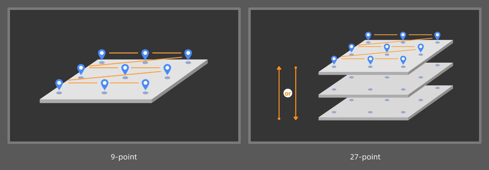
| If high-accuracy 9-point and 27-point calibration is required, ensure during punching that the feature holes are evenly distributed in the machine coordinate system. For example, during a 9-point calibration, ensure that each row has 3 holes, and the spacings between the holes are as equal as possible, and that the line connecting the centers of the 3 feature holes in each row is parallel to the laser line emitted by the laser profiler. |
Acquire Data
To construct a complete set of feature points, the data acquisition method must strictly match the selected Punch mode.
-
One: Each round of data acquisition contains only one hole. Multiple feature points can be obtained through repeated acquisition and processing.
-
Multiple: Each round of data acquisition and processing can produce multiple feature points.
The data acquisition method is described below with the objective of obtaining 9 feature points from the acquired surface data.
-
One punch
-
Multiple punches
There is only one hole in the silicone pad, and the laser profiler needs to acquire data 9 times. The start position of each acquisition is different, but the number of lines scanned remains the same.
| Record the machine coordinates corresponding to the scan start position of the laser profiler for each scan. |
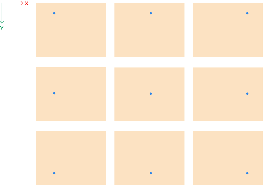
As shown in the figure, during each round of data acquisition, move the laser profiler along its X-axis or Y-axis direction, or move the motion platform carrying the silicone pad, to ensure that the hole appears at a different position in the surface data acquired each time.
| If high-accuracy 9-point and 27-point calibration is required, ensure that the feature points corresponding to each acquisition are evenly distributed in the machine coordinate system during data acquisition. For example, during 9-point calibration, ensure that there are 3 points in each row in the machine coordinate system, and that the line connecting the 3 feature points in each row is parallel to the laser line emitted by the laser profiler. |
There are already 9 holes in the silicone pad, so the laser profiler only needs to acquire data once.
| Record the machine coordinates corresponding to the scan start position of the laser profiler. |
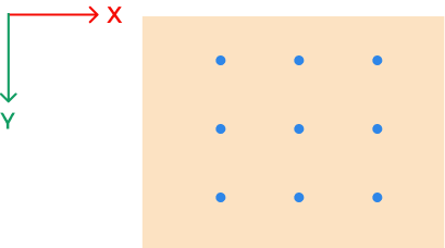
As shown in the figure, during data acquisition, ensure that the FOV of the laser profiler can cover all 9 holes.
Data Preprocessing
-
One punch
-
Multiple punches
-
In the parameter configuration panel of the 3D Laser Profiler Step, confirm whether Tilt Correction is needed.
If the scenario requires high accuracy, it is recommended to perform Tilt Calibration on the laser profiler to eliminate data distortion and measurement errors caused by sensor head mounting tilt. -
Preprocess the surface data. For example, you can use the Process Surface by Filter Step to process the entire image with the Gaussian filter, smoothing the surface noise while preserving the hole edge features, thus ensuring the stability of subsequent feature points.
-
Locate feature points from the feature holes. For example, you can use the Locate Feature Point of Surface Step with the Min Z feature point type to obtain the feature point.
-
Process the surface data acquired in multiple rounds in sequence to obtain a feature point list.
-
Input the feature point list to the N-Point Calibration (3D) Step to start the calibration.
-
In the parameter configuration panel of the 3D Laser Profiler Step, confirm whether Tilt Correction is needed.
If the scenario requires high accuracy, it is recommended to perform Tilt Calibration on the laser profiler to eliminate data distortion and measurement errors caused by sensor head mounting tilt. -
Preprocess the surface data. For example, you can use the Process Surface by Filter Step to process the entire image with the Gaussian filter, smoothing the surface noise while preserving the hole edge features, thus ensuring the stability of subsequent feature points.
-
Locate feature points from the feature holes. For example, you can use the Locate Feature Point of Surface Step with the Min Z feature point type to obtain a feature point list.
-
Input the feature point list to the N-Point Calibration (3D) Step to start the calibration.
Compute Calibration
In the parameter configuration panel of the N-Point Calibration (3D) Step, click the Open the editor button to open the N-Point Calibration window.
| The N-Point Calibration (3D) Step requires the input of a list of feature points. Otherwise, the N-Point Calibration window cannot be opened. |
 Create a Calibration Task
Click the New calibration task button to create a task.
Calibration status is displayed on each task:
-
Not completed: Calibration has not yet been completed. You need to configure the calibration settings on the right side of the window, then Compute calibration and Apply the calibration result to complete the calibration.
-
Completed: Calibration has been completed.
-
Modified: The calibration settings of a completed calibration task have been changed. After you Compute calibration again and Apply the calibration result, or click Revert to last applied, the status changes to Completed.
 Complete Calibration Settings
First, select Punch mode, that is, how the tool performs punches during the calibration process (One or Multiple), and then configure the other parameters.
-
One punch
-
Multiple punches
Each round of data acquisition contains only one hole. Multiple feature points can be obtained through repeated acquisition and processing.
| Parameter | Description |
|---|---|
High accuracy mode |
Can only be enabled for 9-point or 27-point calibration to correct system errors.
|
TCP coordinates |
The TCP pose recorded when the tool performs the punch. |
Axis direction mapping |
The correspondence of X-, Y-, and Z-axis directions between surface data coordinate system and machine coordinate system. Follow the steps below:
|
Point pair settings |
Used to establish the coordinate correspondence between the feature point and the acquisition start position in the machine coordinate system.
|
Each round of data acquisition and processing can produce multiple feature points.
| Parameter | Description |
|---|---|
High accuracy mode |
Can only be enabled for 9-point or 27-point calibration to correct system errors.
|
Acquisition start position |
The start position of the first data acquisition in the machine coordinate system. |
Axis direction mapping |
The correspondence of X-, Y-, and Z-axis directions between surface data coordinate system and machine coordinate system. Follow the steps below:
|
Point pair settings |
Used to establish the coordinate correspondence between the feature point and the tool center point (TCP).
|
After parameter configuration, click the Compute calibration button to obtain the calibration result.
 View Calibration Results
| Calibration Parameter | Description |
|---|---|
Transformation matrix |
Euclidean transformation matrix from surface data coordinates to machine coordinates. |
Reprojection errors |
The reprojection errors from the surface data coordinates to the machine coordinates. Generally, the smaller the reprojection errors, the better. |
If the calibration result does not meet the requirements, you can continue adjusting the actual installation and acquisition settings, update the calibration settings, and then compute calibration again.
After confirming the calibration results, click the Apply button to apply the current calibration settings and save the calibration results.
Apply Calibration Results
The N-point calibration results are saved in the calibration folder under the solution folder and can be used by the 3D Laser Profiler Step in any project within the current solution.
The procedure is as follows:
-
In the parameter configuration panel of the Step, set Camera Mode to One.
-
Select Apply N-Point Calibration, and the Select Calibration Result parameter will be displayed in the parameter panel. Then, select the calibration result to use from the drop-down menu.
-
Configure Acquisition Start Position X/Y/Z, that is, the X, Y, and Z coordinates of the start position where the laser profiler begins data acquisition in the machine coordinate system.
-
After configuring other parameters of the Step, you can run the Step to apply the selected calibration result.
After applying the N-point calibration result in the project and obtaining feature points from the surface data, you can use the Transform Poses of Feature Points (Gantry) Step to convert the feature point coordinates into the machine coordinate system, thereby guiding subsequent trajectory planning and execution of the machine.
Troubleshooting
Calibration Failed
Symptom: In the N-Point Calibration window, after clicking the Compute calibration button, a pop-up message says “Calibration failed.”
Possible causes:
-
High accuracy mode is enabled, but the number of feature points is not 9 or 27.
-
The number of feature points is less than three.
-
An internal error occurred in the software.
Solutions:
-
Ensure that High accuracy mode is enabled only when the number of feature points is 9 or 27.
-
Ensure that the number of feature points used for calibration is no less than three.
-
Contact Technical Support.