Mitsubishi MELSEC
Mech-MSR supports communication with external devices through Mitsubishi MELSEC. Before you read the following content, make sure that the communication configuration has been completed in Mech-MSR.
About Mitsubishi MELSEC
Mitsubishi MC Series PLCs communicate with the Mech-MSR software through the MC protocol. Under this communication mode, Mech-MSR acts as the client, and the PLC acts as the server.
Communication Workflow
The structure type used for communication occupies 200 D registers in total. The base address of the struct variables must match the configured Register(D) base address in Mech-MSR.
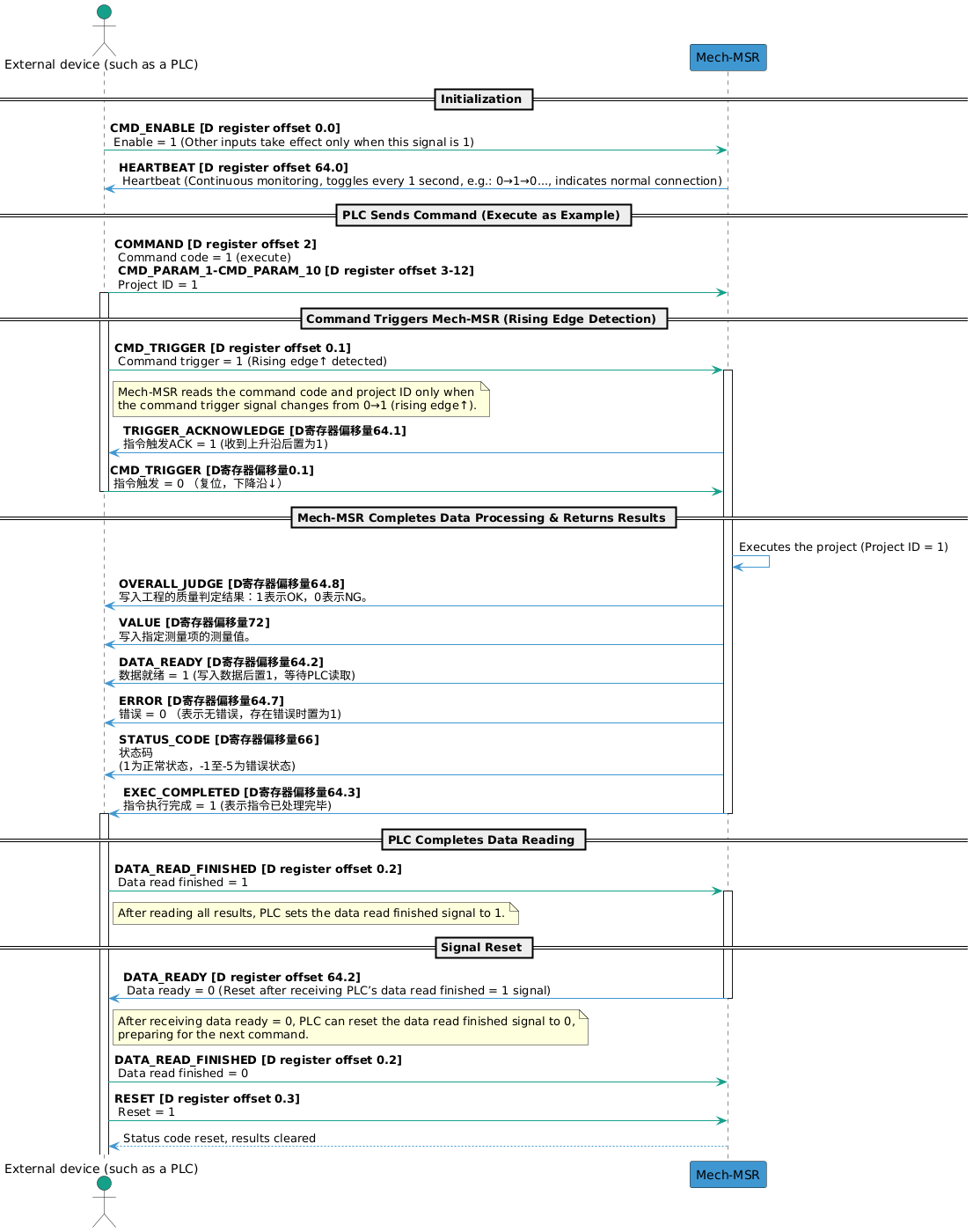
The process of Mitsubishi MELSEC communication is shown in the following figure.
|
Input Signals (from the PLC to Mech-MSR)
| Name | Description | Data type | D Register Offset |
|---|---|---|---|
The signal to enable the command. |
Boolean |
0.0 |
|
The signal to trigger the command. |
Boolean |
0.1 |
|
The data is read. |
Boolean |
0.2 |
|
The output data is reset. |
Boolean |
0.3 |
|
BIT_SPARE_1 |
A reserved field. |
Boolean |
0.4 |
BIT_SPARE_2 |
A reserved field. |
Boolean |
0.5 |
BIT_SPARE_3 |
A reserved field. |
Boolean |
0.6 |
BIT_SPARE_4 |
A reserved field. |
Boolean |
0.7 |
BIT_SPARE_5 |
A reserved field. |
Boolean |
0.8–0.15 |
WORD_SPARE_1 |
A reserved field. |
Word[Signed] |
1 |
Command code. |
Word[Signed] |
2 |
|
CMD_PARAM_1 |
The command parameter 1. |
Word[Signed] |
3 |
CMD_PARAM_2 |
The command parameter 2. |
Word[Signed] |
4 |
CMD_PARAM_3 |
The command parameter 3. |
Word[Signed] |
5 |
CMD_PARAM_4 |
The command parameter 4. |
Word[Signed] |
6 |
CMD_PARAM_5 |
Command parameter 5 |
Word[Signed] |
7 |
CMD_PARAM_6 |
Command parameter 6 |
Word[Signed] |
8 |
CMD_PARAM_7 |
Command parameter 7 |
Word[Signed] |
9 |
CMD_PARAM_8 |
Command parameter 8 |
Word[Signed] |
10 |
CMD_PARAM_9 |
Command parameter 9 |
Word[Signed] |
11 |
CMD_PARAM_10 |
Command parameter 10 |
Word[Signed] |
12 |
VAR_1 |
Variable 1 |
Float |
13–14 |
VAR_2 |
Variable 2 |
Float |
15–16 |
VAR_3 |
Variable 3 |
Float |
17–18 |
VAR_4 |
Variable 4 |
Float |
19–20 |
VAR_5 |
Variable 5 |
Float |
21–22 |
VAR_6 |
Variable 6 |
Float |
23–24 |
VAR_7 |
Variable 7 |
Float |
25–26 |
VAR_8 |
Variable 8 |
Float |
27–28 |
VAR_9 |
Variable 9 |
Float |
29–30 |
VAR_10 |
Variable 10 |
Float |
31–32 |
WORD_SPARE_2 |
A reserved field. |
Word[Signed] |
33–63 |
CMD_TRIGGER
Mech-MSR reads the command code and command parameters only when the command trigger signal changes from 0 to 1 (rising edge). After Mech-MSR returns the Trigger Acknowledge signal, the command trigger signal can be set to 0.
DATA_READ_FINISHED
After the PLC finishes reading the data, set this signal to 1. Only after the Data Ready signal changes to 0 can this signal be set to 0.
RESET
When this signal is set to 1, the PLC clears the received judgement result and measurement result. At this point, the PLC can send new commands and status code signals are reset.
COMMAND
The following table lists the supported commands in the current protocol and their corresponding command codes, command parameters, and descriptions.
| Command | Command Code | Command Parameter | Description |
|---|---|---|---|
execute |
1 |
Project ID. Only 1 project ID can be set at a time. |
Used to trigger a project to run and obtain the project’s judgment results and measurement results. |
trigger |
2 |
Project ID. 1 to 4 project IDs can be set at a time. |
Used to trigger a project to run. |
return |
3 |
Project ID. Only 1 project ID can be set at a time. |
Used to obtain the judgment results and measurement results of the specified project. |
judge |
4 |
Used to obtain the overall quality judgment result of the specified project or the quality judgment results of individual measurement items. |
|
value |
5 |
Used to obtain the measured values of the specified project. |
|
recipe |
6 |
Project ID and parameter recipe ID. |
Used to switch the parameter recipe used by a project. |
solution |
7 |
Solution ID. |
Used to switch a solution. |
SetNumVar |
8 |
Global variable ID. Only 1 can be set at a time. |
Used to set the value of a numeric global variable. The variable value is passed through VAR_INPUT. |
GetNumVar |
9 |
Global variable ID. Only 1 can be set at a time. |
Used to read the value of a numeric global variable. The result is returned through VALUE. |
|
VAR_INPUT
When the SetNumVar command is executed, the set value is written to VAR_INPUT.
| Name | Description | Data type | D Register Offset |
|---|---|---|---|
VAR_1 |
Variable 1 |
Float |
13–14 |
VAR_2 |
Variable 2 |
Float |
15–16 |
VAR_3 |
Variable 3 |
Float |
17–18 |
VAR_4 |
Variable 4 |
Float |
19–20 |
VAR_5 |
Variable 5 |
Float |
21–22 |
VAR_6 |
Variable 6 |
Float |
23–24 |
VAR_7 |
Variable 7 |
Float |
25–26 |
VAR_8 |
Variable 8 |
Float |
27–28 |
VAR_9 |
Variable 9 |
Float |
29–30 |
VAR_10 |
Variable 10 |
Float |
31–32 |
Output Signals (from Mech-MSR to the PLC)
| Name | Description | Data type | D Register Offset |
|---|---|---|---|
The heartbeat signal. |
Boolean |
64.0 |
|
The trigger acknowledge signal, which acknowledges the command trigger signal. |
Boolean |
64.1 |
|
The data ready signal. |
Boolean |
64.2 |
|
The execution completed signal, which indicates that the command execution is completed. |
Boolean |
64.3 |
|
BIT_SPARE_1 |
A reserved field. |
Boolean |
64.4 |
BIT_SPARE_2 |
A reserved field. |
Boolean |
64.5 |
BIT_SPARE_3 |
A reserved field. |
Boolean |
64.6 |
The error signal. |
Boolean |
64.7 |
|
The overall judge signal. |
Boolean |
64.8 |
|
BIT_SPARE_4 |
A reserved field. |
Boolean |
64.9–64.15 |
WORD_SPARE_1 |
A reserved field. |
Word[Signed] |
65 |
Status code. |
Word[Signed] |
66 |
|
WORD_SPARE_2 |
A reserved field. |
Word[Signed] |
67 |
The judge signal. |
Boolean (0–63) |
68 |
|
Measurement results and variable values |
Float (0–63) |
72 |
HEARTBEAT
System heartbeat. It toggles every second. It can be used to determine whether the communication connection between the PLC and Mech-MSR is normal or disconnected.
TRIGGER_ACKNOWLEDGE
When Mech-MSR receives the rising edge of the Command Trigger signal, this signal is set to 1. When a falling edge is detected for the command trigger signal, this signal is set to 0.
DATA_READY
Mech-MSR writes data to the output port and waits for the PLC to read it. When the Data Read Finished signal is 1, this signal is set to 0.
EXEC_COMPLETED
When command execution ends, this signal is set to 1, indicating that the command has been processed.
ERROR
When the status code returned by Mech-MSR is not 1, this signal is set to 1 to indicate an error.
OVERALL_JUDGE
Overall judgment result of the project. 1 indicates pass (OK), and 0 indicates fail (NG).
| Quality judgment rules must be configured for the project in Mech-MSR’s Output Management window, and the measurement items considered during quality judgment must be determined. Only after the configuration is complete can valid quality judgment results be obtained. |
STATUS_CODE
Mech-MSR may return the following status codes:
-
Normal status code: 1, indicating that the command was executed successfully.
-
Error status codes: -1, -2, -3, -4, and -5. See Error Codes for details.
JUDGE
Judgement results were added for measurement items on the Communication output tab in the Output Management window. 1 indicates OK, and 0 indicates NG.
| Up to 64 judgment results can be output at one time for a single project. |
VALUE
The VALUE module can return the following data:
-
Measurement results are added for measurement items on the Communication output tab in the Output Management window.
-
The values of numeric global variables are read when the
GetNumVarcommand is executed.
| Up to 64 measurement values can be output at one time for a single project. |