Detect and Fit Rectangle
Description
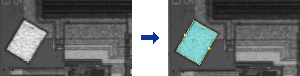
This Step is used to detect the edges of a rectangle from an image and fit the rectangle.
Usage Scenario
This Step is primarily used in scenarios such as detecting rectangular areas, reference frames, pads, and patch areas on workpieces, where there is a rigid requirement for rectangle positioning or dimensional measurement.
Basic Concepts
-
Caliper
In image processing, a virtual measurement tool detects edges within a specified region. Adjusting its count, width, and length affects the accuracy and stability of edge detection.
-
Edge Polarity
It refers to the direction of grayscale change across an edge, e.g., dark-to-light or light-to-dark.
Workflow
The process of configuring this Step is shown below:

-
Configure the input. Connect the Step ports in the graphical programming workspace or select the input under Input in the parameter configuration panel.
-
Complete the ROI Settings.
-
Set other parameters.
-
Confirm the output items in the Output section.
-
Run the Step, and view output.
Input Description
| Input Item | Description |
|---|---|
Image |
Image used to detect rectangular edges |
Alignment Parameter Group |
Used to adjust the ROI’s pose in sync with the target object’s pose changes. |
Parameter Description
| Parameter | Description |
|---|---|
ROI Settings |
You can draw a rectangular ROI. The system extracts multiple columns of pixels according to the caliper settings, and the detected edge points in each column will be used for rectangular fitting. For a closed ROI, such as a rectangle, the calipers detect edges outward from the inside of the ROI. The caliper direction generally does not need adjustment, and rotating the ROI does not change the detection direction. See 2D ROI Settings to learn more about ROI and calipers. |
Edge Polarity |
This parameter specifies the direction in which the grayscale values change at the edges. Value list:
|
Filter Window Size |
Specify the window size to be used when filtering each column of pixels in its direction. Filtering can reduce noise and improve the stability of edge detection results. |
Edge Type |
Define the edge types to be retained in edge detection. Value list: Best, First, Last. |
Gray Value Change Threshold |
This parameter specifies the minimum gray value change between adjacent pixels at the edge of an extracted pixel column required for edge point detection. Setting this parameter value properly can effectively filter out weak edges and noise. |
Use Relative Threshold |
Once selected, an edge point is detected only if the gray value change between adjacent pixels at the edge of a pixel column meets or exceeds the specified percentage of the maximum change in that column. Once this parameter is selected, set Relative Threshold. |
Max Distance Threshold |
This parameter is used to set the maximum allowed distance from detected edge points to the fitted rectangle. Edge points with a distance less than or equal to this threshold are considered inliers. Default value: 4 px |
Min Fit Score |
This parameter is used to determine the lowest score for determining whether the fitted result is acceptable. It is only used for result evaluation and will not affect the fitting process. The score equals the ratio of the number of inliers to the total number of edge points. When high measurement accuracy is required, raise Min Fit Score. A typical value is 0.8 or above. Default value: 0.7 |
Max Iterations |
The maximum number of attempts the algorithm will make to fit an optimal rectangle. Iteration stops once this limit is reached. When the target contour is complex or subject to high interference, increasing the number of iterations improves accuracy at the cost of increased processing time. Default value: 1000 |
Output Description
Select the output item(s) to add the output port(s) to the Step, and the corresponding data will be output after the Step is run. You can select the output according to the actual measurement requirements.
| If you select an expandable output item, you must expand it by clicking ▶, and then set the Lower Limit and Upper Limit values to determine the acceptable range. If the output value falls within the acceptable range, the measurement item is judged as OK; otherwise, it is judged as NG. |
| Output Item | Description |
|---|---|
Rectangle Pose |
The position and orientation of the fitted rectangle. |
Center Point |
The geometric center of the fitted rectangle. |
Center X |
The X coordinate of the center point of the fitted rectangle. |
Center Y |
The Y coordinate of the center point of the fitted rectangle. |
Rectangle Width |
The width of the fitted rectangle. |
Rectangle Height |
The height of the fitted rectangle. |
Rectangle Rotation Angle |
The rotation angle of the fitted rectangle, relative to the positive X-axis direction. |
Fitted Rectangle |
The rectangle obtained through fitting. |
Troubleshooting
|
CV-W8701
Error: Invalid ROI settings.
Possible cause: The size of the ROI is too large, more than twice the size of the image.
Solution: Reset the ROI to ensure that it is of a proper size.
CV-W8702
Error: The set “Caliper Length” value is outside of the valid range.
Solution: Ensure the parameter value is within the range of 0–10000.
CV-W8703
Error: The set “Caliper Center Spacing” value is outside of the valid range.
Solution: Ensure the parameter value is within 0–1000.
CV-W8704
Error: The set “Caliper Width” value is outside of the valid range.
Solution: Ensure the parameter value is within the range of 0 to 100.
CV-W8705
Error: The set “Filter Window Size” value is outside of the valid range.
Solution: Ensure the parameter value is within the range of 0 to 100.
CV-W8706
Error: The set “Edge Polarity” is invalid.
Solution: Select valid edge polarity from the drop-down list.
CV-W8707
Error: The set “Edge Type” is invalid.
Solution: Select a valid edge type from the drop-down list.
CV-W8708
Error: The set “Gray Value Change Threshold” value is outside of the valid range.
Solution: Ensure the parameter value is within the range of 0 to 255.
CV-W8709
Error: The set “Relative Threshold” value is outside of the valid range.
Solution: Ensure the parameter value is within the range of 0% to 100%.
CV-W8710
Error: Unable to fit a rectangle since the detected edge points are insufficient.
Possible causes:
-
Invalid ROI settings.
-
The calipers are not set properly.
-
The “Gray Value Change Threshold” and “Relative Threshold” values are too large.
-
The selected “Edge Polarity” is not set properly.
Solution:
-
Ensure that the ROI is not too small.
-
Adjust the caliper settings to ensure edge points can be detected from the calipers.
-
Lower the “Gray Value Change Threshold” and “Relative Threshold”.
-
Ensure that the “Edge Polarity” parameter is set properly.
CV-W8711
Error: Unable to fit a rectangle since the detected edge points are insufficient.
Possible causes:
-
Invalid ROI settings.
-
The calipers are not set properly.
-
The “Gray Value Change Threshold” and “Relative Threshold” values are too large.
-
The selected "Edge Polarity" is not set properly.
Solution:
-
Ensure that the ROI is not too small.
-
Adjust the caliper settings to ensure edge points can be detected from the calipers.
-
Lower the “Gray Value Change Threshold” and “Relative Threshold”.
-
Ensure that the “Edge Polarity” parameter is set properly.
CV-W8713
Error: The “Min Fit Score” must be within the range [0, 1].
Solution: Ensure the parameter value is within [0, 1].