Tilt Calibration (Automatic)
Overview
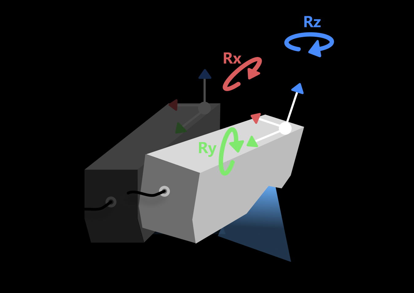
Tilt calibration (automatic) is a calibration method in which the system scans a standard calibration block and automatically calculates the actual mounting tilt angle (direction vector) of the sensor head. Using the known geometric features of the calibration block, this method analyzes the spatial relationship between two sets of scan data to calculate the sensor head’s mounting tilt angles about the X, Y, and Z axes, and generates correction parameters for real-time tilt correction in subsequent measurements.
Automatic calibration does not require manual angle measurement, offers high accuracy and good repeatability, and is suitable for laboratory or production-line scenarios with high accuracy requirements and controlled environments.
| The laser profiler calibration feature is available after a solution is opened, and the calibration results apply to all projects in that solution. |
Start the Feature
You can open the Tilt Calibration (Automatic) window in the following way:
-
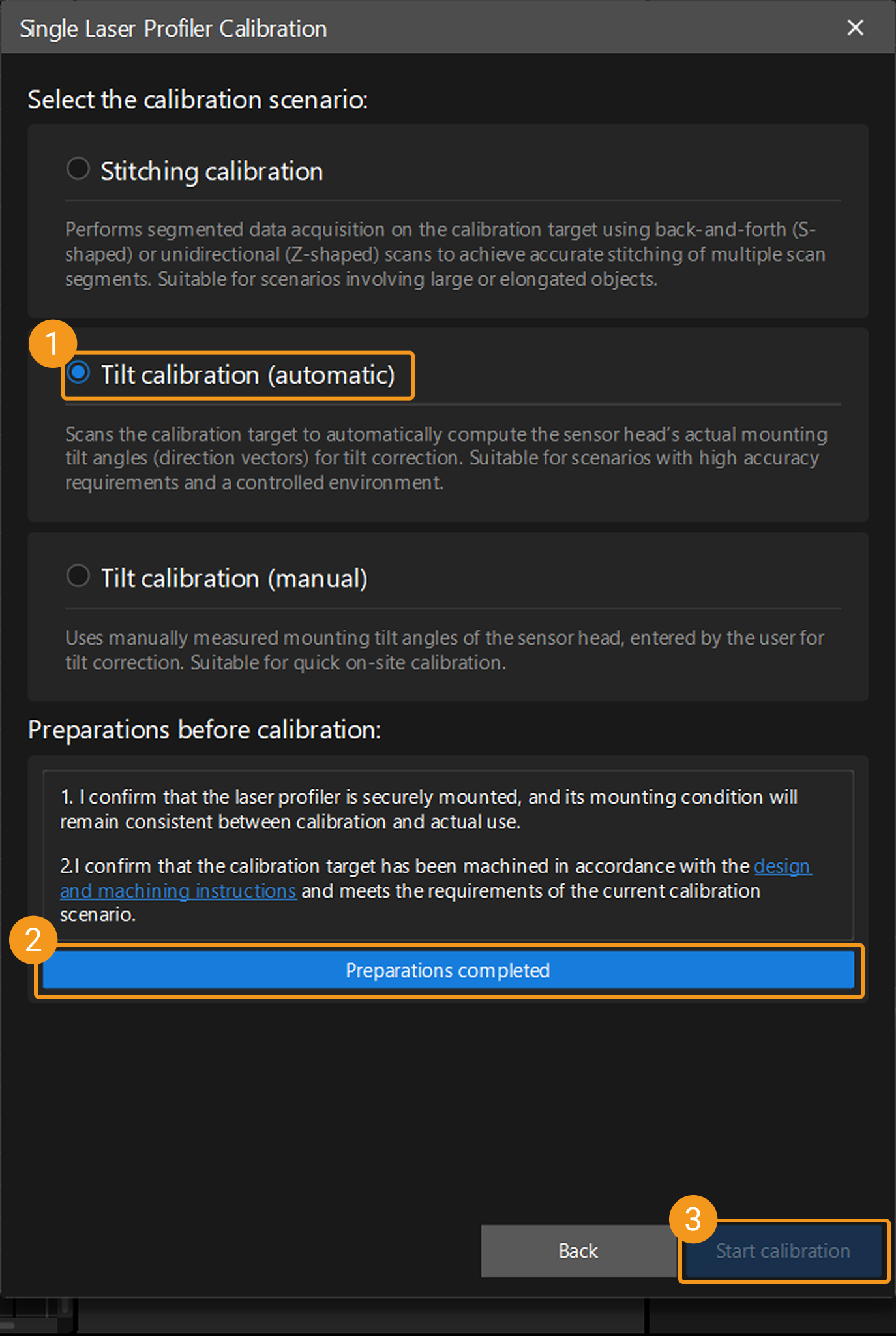
On the Mech-MSR main interface, click the Laser Profiler Calibration button on the toolbar to open the laser profiler calibration window. After selecting Single, the Single Laser Profiler Calibration window opens, where you can select the Tilt calibration (automatic) scenario.
-
Select in the menu bar to open the Laser Profiler Calibration window. After selecting Single, the Single Laser Profiler Calibration window opens, where you can select the Tilt calibration (automatic) scenario.
Calibration Procedure
Preparation
Before starting the calibration, ensure that the following preparations have been completed:
-
Confirm that the laser profiler is securely mounted and its mounting condition remains consistent during calibration and actual use.
-
Confirm that the calibration block that meets the requirements of the current scenario has been fabricated according to the calibration block design and fabrication instructions, and ensure that its placement meets the requirements.
-
Ensure that the Mech-Eye Viewer and Mech-MSR can connect to the laser profiler normally.
-
In the Mech-Eye Viewer software, adjust the parameters to ensure that the acquired image data has no obvious missing regions and contains minimal noise, and save the parameter group as the configuration parameter group for the laser profiler during calibration.
-
To ensure calibration accuracy, warm up the laser profiler before calibration by continuously acquiring data for more than one hour after power-on under the actual operating parameters.
Instructions
 Connect to Laser Profiler
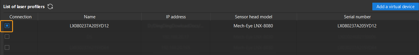
You can select laser profilers in the Connection column to connect to the devices.
|
After connecting the laser profiler, click the Next button to go to calibration target settings.
 Calibration Target Settings
Enter the required geometric parameters based on the type of calibration block prepared.
-
Confirm the calibration block type.
-
Target with one frustum
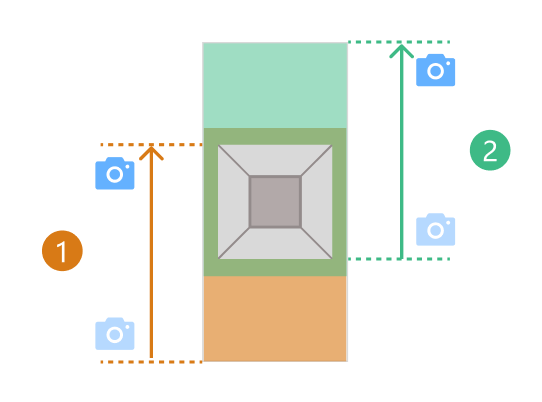
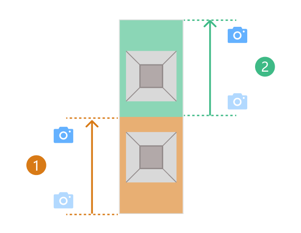
The laser profiler must scan the same frustum on the calibration target from two different starting positions. The data acquired in each scan must include the complete surface of the corresponding frustum and the surface on which the frustum is located. The two scans are shown as ① and ② in the figure below.
-
Target with two frustums
The laser profiler must scan two different frustums on the calibration target separately. The data acquired in each scan must include the complete surface of the corresponding frustum and the surface on which the frustum is located. The two scans are shown as ① and ② in the figure below.
-
-
Configure calibration target parameters.
Enter the parameter values based on the calibration target actually used.
Be sure to enter accurate parameter values. 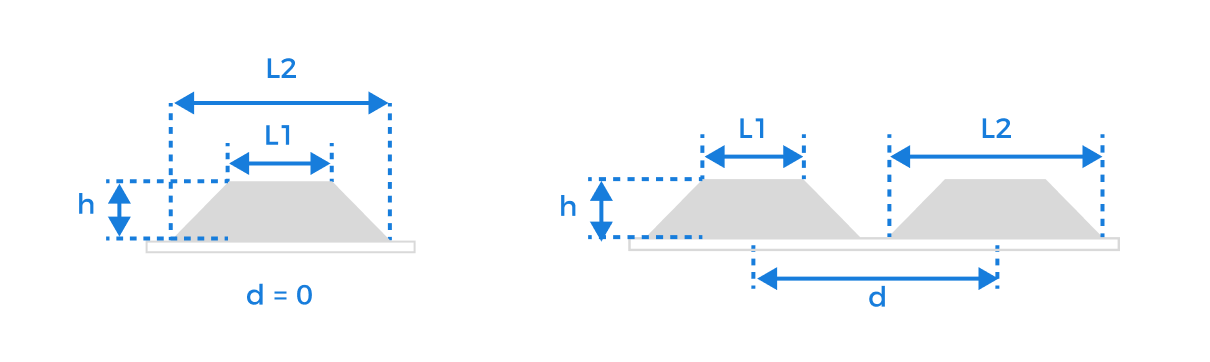
Parameter
Description
Upper base length (L1)
The side length of the frustum’s smaller base, in millimeters (mm).
Lower base length (L2)
The side length of the frustum’s larger base, in millimeters (mm).
Frustum height (h)
The vertical distance from the upper base to the lower base of the frustum, in millimeters (mm).
Translation distance (d)
The distance between the centerlines of neighboring frustums, in millimeters (mm).
When multiple frustums are arranged side by side on the calibration target, translating neighboring frustums by this distance will cause them to coincide.
After entering the accurate parameter values and confirming that they are correct, click the Next button to go to the calibration page.
 Compute Calibration
Follow the steps below to complete calibration:
-
Set relative direction of motion between the calibration target and the laser profiler, and specify the configuration parameter group to be used for subsequent data acquisition.
Based on the actual motion relationship, select whether the motion direction of the calibration target is the same as or opposite to the Y-axis direction of the laser profiler. This setting is used to ensure correct coordinate system mapping.
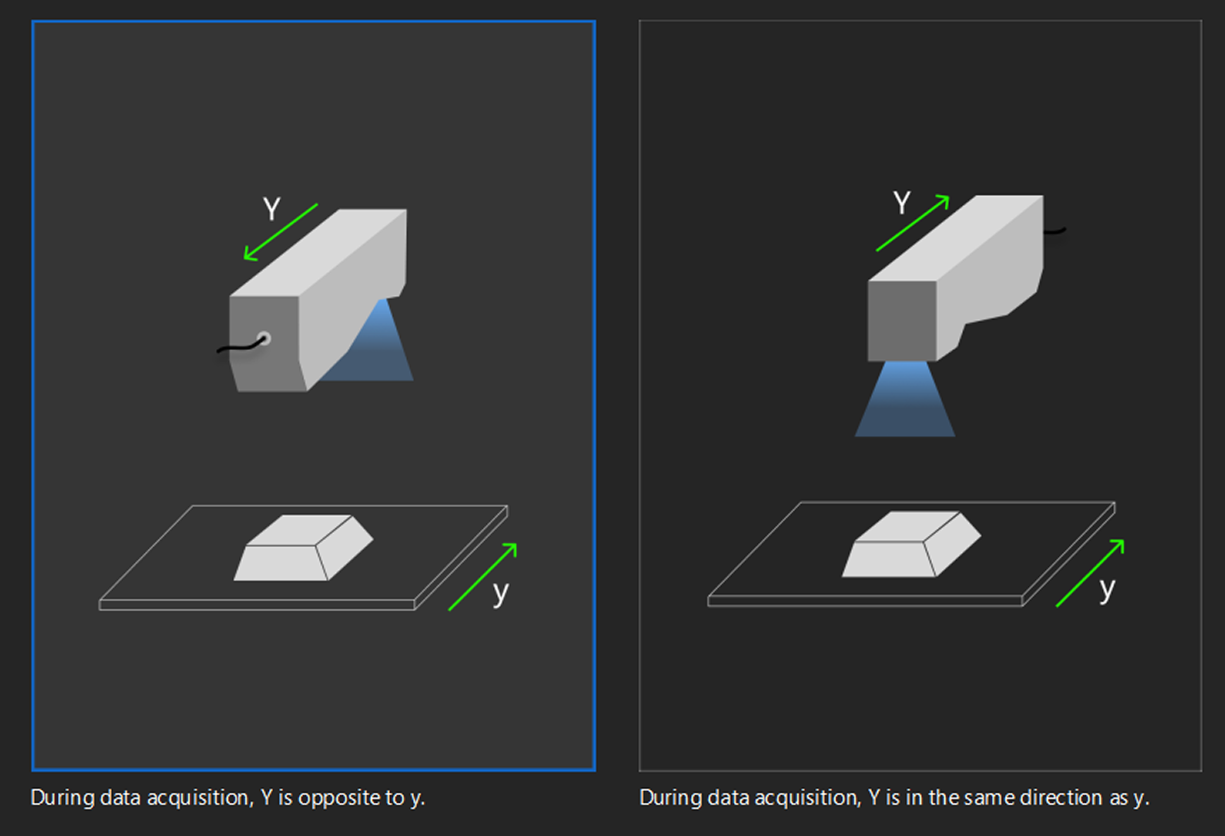
After configuration, click Next to start data acquisition.
-
Acquire data.
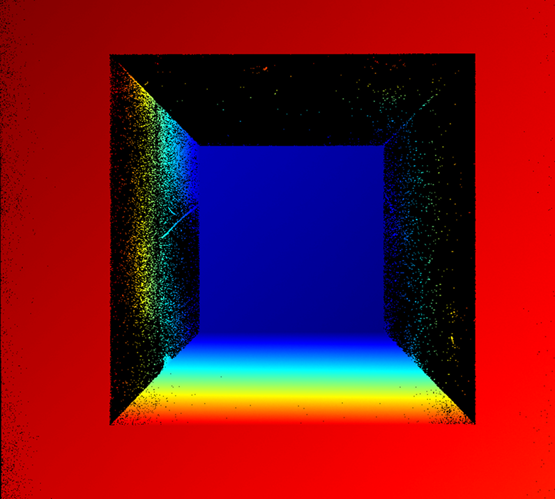
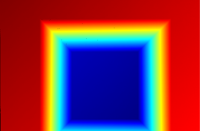
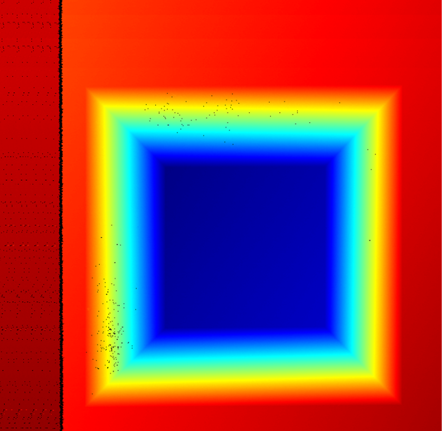
Based on the type of calibration target in use, determine the starting positions for the two acquisitions, and then click the Start acquisition button to complete the data acquisition in sequence. After each round of data acquisition, check whether the image data meets the following requirements:
-
The calibration target should be located at the image center.
-
The image should contain only the six feature surfaces of the calibration target, and each surface should be fully captured.
If other surface data is present, enable Use feature region and adjust its size and position to ensure that the region contains only the six feature surfaces of the calibration target. -
The image should have minimal noise.
Normal Severe point loss Incomplete surface Extra surface present Excessive noise 
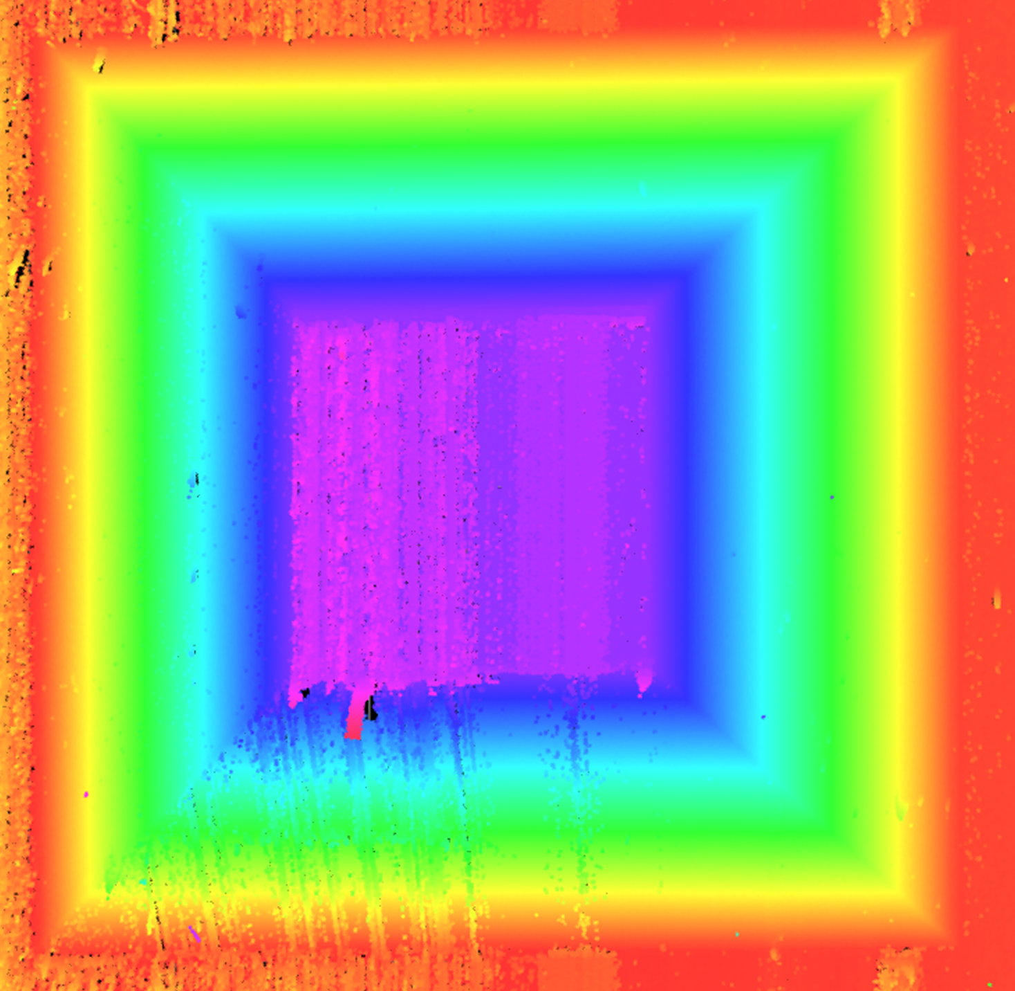
If the quality of the acquired data does not meet the requirements, readjust the parameters in the Mech-Eye Viewer software until the image quality meets the requirements, and then save the parameter group. Then return to step 1 and re-select the Configuration parameter group.
After data acquisition is complete, click the Next button to start the calibration calculation.
-
-
Compute calibration.
Click the Compute calibration button to start multiple calibrations. The system will automatically analyze the geometric relationship between the two scans, calculate the actual mounting tilt angle (direction vector) of the sensor head, and generate the calibration result.
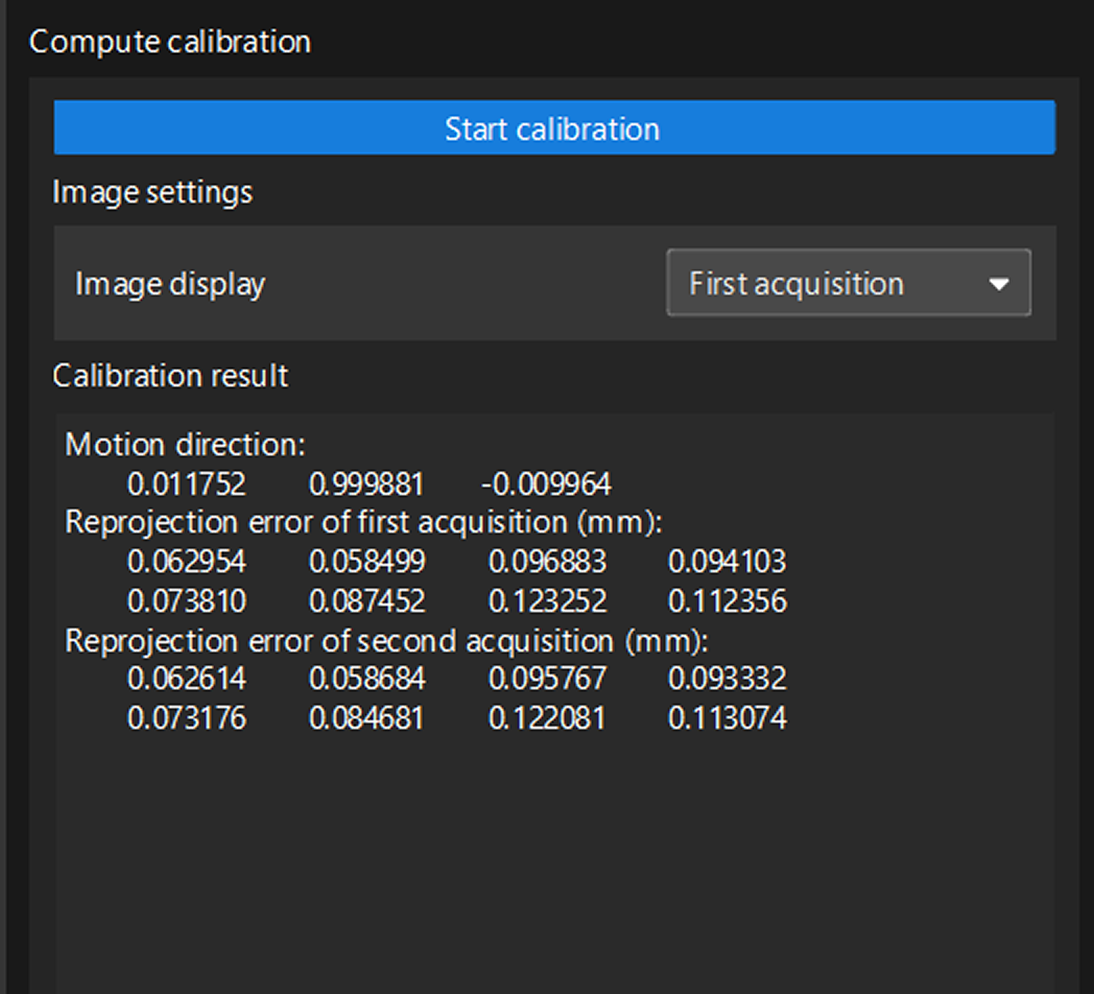
-
Check the calibration result to ensure that the calibration accuracy meets the requirements.
After confirming that the calibration result is correct, click the Save. In the pop-up window that appears, specify the file name and storage path to save the calibration result and complete the calibration.
Apply Calibration Result
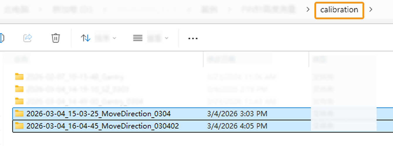
Tilt calibration (automatic) results are saved in the calibration folder under the solution folder and can be used by the 3D Laser Profiler Step in any project in the current solution.
The procedure is as follows:
-
In the parameter configuration panel of the Step, change the Camera Mode to One.
-
Select the Tilt Correction parameter. The Select Calibration Result parameter is then displayed in the parameter panel. Choose the calibration result to use from the drop-down menu.
-
After configuring the other parameters of this Step, run the Step to apply the selected calibration result.