Configure Custom Communication Service - Modbus TCP Slave
This section describes how to configure a custom communication service of the Modbus TCP Slave type in Mech-MSR.
Configuration Process
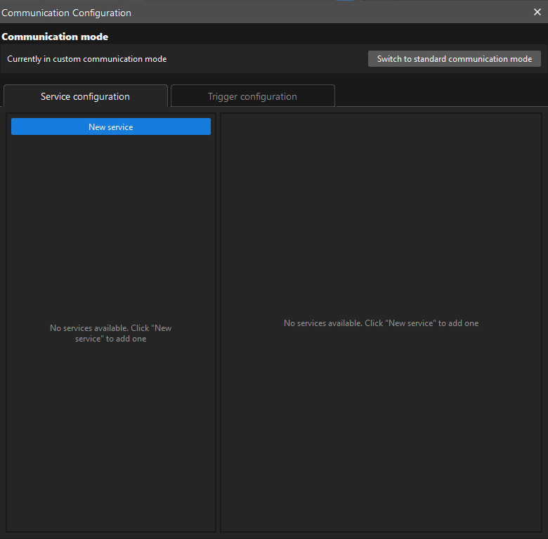
| Before configuring, click Communication Configuration on the software toolbar and confirm that the software is currently using the custom communication mode. |
To configure a custom communication service of the Modbus TCP Slave type, perform the following steps:
-
On the Service configuration tab of Communication Configuration, click New service.
-
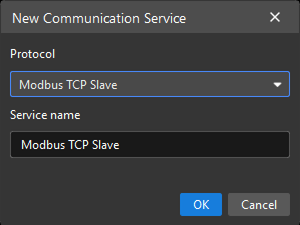
In the New Communication Service dialog box, set Protocol to Modbus TCP Slave, specify Service name, and then click OK.
-
In the service list on the left, click the newly created service. Its configuration interface is displayed on the right.
-
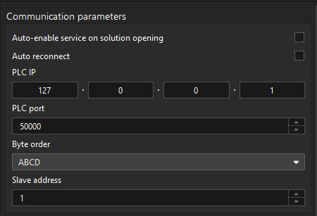
In the Communication Parameters area, set parameters as needed.
-
Auto-enable the service when opening the solution: If you want the software to automatically enable the service the next time the solution is opened, select this option.
-
Auto reconnect: When this option is enabled, the service automatically attempts to reconnect after the connection to the Modbus slave is lost. Enable it as needed.
-
PLC IP: Specifies the IP address of the remote Modbus slave. Make sure that the Modbus slave IP address is correctly configured and reachable. The Modbus slave IP address and the IPC IP address must be on the same subnet.
-
PLC port: Specifies the port of the remote Modbus slave. The default value is 50000. Adjust it according to the actual port of the Modbus slave.
-
Byte order: Select DCBA for standard big-endian floating-point data, or ABCD for standard little-endian floating-point data, according to the floating-point byte order used by the slave.
-
Slave address: The device address of the remote Modbus slave. The default value is 1.
-
-
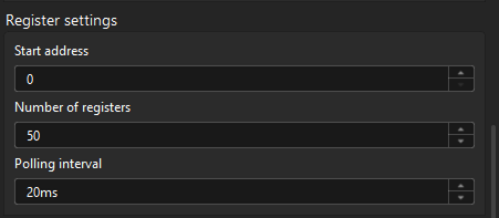
In the Register Settings area, set parameters as needed.
-
Start address: Specifies the register address in the PLC from which data read and write operations start. After this parameter is set, Modbus TCP Slave starts from this address and accesses subsequent registers. The default value is 0.
-
Number of registers: Specifies the number of consecutive registers to read or write in each communication operation. For example, if this parameter is set to 10, Modbus TCP Slave starts from the start address and accesses 10 consecutive registers. The default value is 50.
-
Polling interval: Specifies the time interval at which Modbus TCP Slave sends data read or write requests to the PLC, in milliseconds. The default value is 20 ms. A shorter polling interval updates data faster but increases system load. A longer polling interval updates data more slowly but reduces system load. Adjust it as needed.
-
-
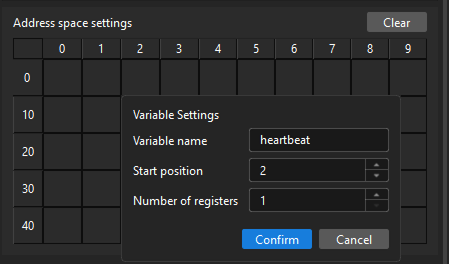
In the Address Space Settings area, bind registers to variables for specific functions, such as the heartbeat variable used for heartbeat checks:
-
Select a target register, and then click the edit icon.
-
In the Variable Settings dialog box, specify Variable name, Start position, and Number of registers, and then click Confirm.
-
The address spaces occupied by any two register variables must not overlap.
-
To modify the settings of a register variable, click the edit icon again, and then modify the settings in the Variable Settings dialog box.
-
To delete the settings of a register variable, select the space occupied by the register variable, and then click the delete icon. Deleting a register variable also deletes the trigger configurations associated with it.
-
-
-
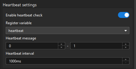
In the Heartbeat Settings area, enable heartbeat checks as needed, and configure heartbeat parameters.
-
Register variable: Specifies the register variable used to store heartbeat signals. Make sure that this variable is configured correctly and allows write operations. Modbus TCP Slave periodically writes heartbeat messages to this variable.
-
Heartbeat message: Specifies the values alternately written to the register variable during heartbeat checks. These are usually two different integers, such as 1 and 0. Modbus TCP Slave alternately writes these two values in each heartbeat cycle. The PLC can determine whether communication is normal by detecting changes to this variable.
-
Heartbeat interval: Specifies the time interval between two heartbeat message writes, in milliseconds (ms). Set it according to actual communication requirements. The default value (1000 ms) is recommended. A shorter interval detects disconnections sooner but increases communication frequency.
-
After the configuration is complete, you can start the communication service.
For a custom communication service of the Modbus TCP Slave type, the service attempts to establish a connection to the Modbus slave when it starts. If the connection cannot be established, the communication service cannot start. Troubleshoot according to the error dialog box.