Getting Started with Measurement Mode
Please prepare some objects with circular parts first. In this application, you can utilize the measurement mode to check if the radius of the circle conforms to the specification or not.
Create a New Project and Switch to Measurement Mode
-
Go to , check Measurement project in Measurement Settings, and then restart the software;
-
Select to create a new project;
-
Click
 in the toolbar to switch to measurement mode.
Input
The source data can be input via the following Steps:
-
Laser Profiler
The Steps Laser Profiler and Read Point Cloud V2 should be connected with Orthographic Projection when utilizing Steps that belong to 2.5D Measuring algorithm.
Capture Images from Camera is used to input source data in the application below.
-
Locate Capture Images from Camera in Step Library and drag it into the graphical programming workspace.
|
You can click > in the lower right corner of Step Library to switch the display format of the Steps. |
-
Please refer to Capture Images from Camera to configure the parameters in this Step.
Processing
This example aims to check if the circular part of the object conforms to the specification or not, so the Step Measure Circles is used.
-
Locate the Step:
Go to Measuring ‣ 2D Measuring in the Step Library, and drag the Step Measure Circles into the graphical programming workspace.
-
Connect Steps:
Select Measure Circles, and then select Capture Images from Camera_1_Camera Color Image as Input 1 (Color Image) in the Step Input Source Selection panel.
|
The type of input data should be consistent with that of the input port. If the types of data and port do not match, an alert will pop up. |
-
Run the project:
Click Run in the top middle of the graphical programming workspace or click
 of the Step Capture Images from Camera to run the project. Then the color image will appear in the sketchpad area.
 -
Select the circular part for detection:
Click Measure Circles first. The select frame is in the upper left corner of the image. It is recommended to zoom out the image first and then adjust the frame to a proper size. Then you can drag it to the circular part in the image and therefore select an ROI.
The sketchpad is used for visualization, selecting an ROI, and adding points:
-
You can switch the image display type between color image, gray image, and binary image by clicking the buttons in the upper left corner.
-
You can click the buttons in the upper right corner of the sketchpad to zoom in or out the image, restore the image scale to 100%, and adjust the Pen Width, Background Brightness, Background Contrast and Font Size.
|
You can also scroll upwards or downwards to zoom in or out the image. |
Output
-
Read the measurement:
-
The radius of the circle in the ROI will be displayed in the sketchpad area in real-time;
-
The value will be displayed in the Measurement Output panel as well.
-
-
Determine whether the measurement conforms to the specification or not:
The measurement result is displayed in red, which represents that the result failed to meet the requirement. In this example project, it is because that the LSL (lower specification limit) and USL (upper specification limit) have not been set:
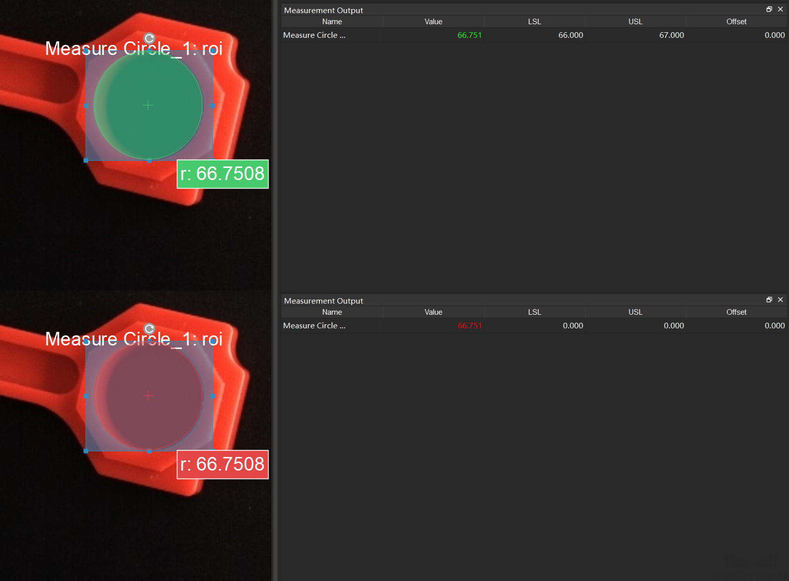
After setting the LSL and USL according to actual situation, if the measurement falls within the lower and upper limits, the value will be displayed in green, as shown below.
-
Result View:
The Result View in Measurement Mode provides a more user-friendly display of the measurement result. Click
 , and select Result View. The result will be displayed in the upper left corner: OK represents that the result conforms to the specification, while NG represents the opposite.
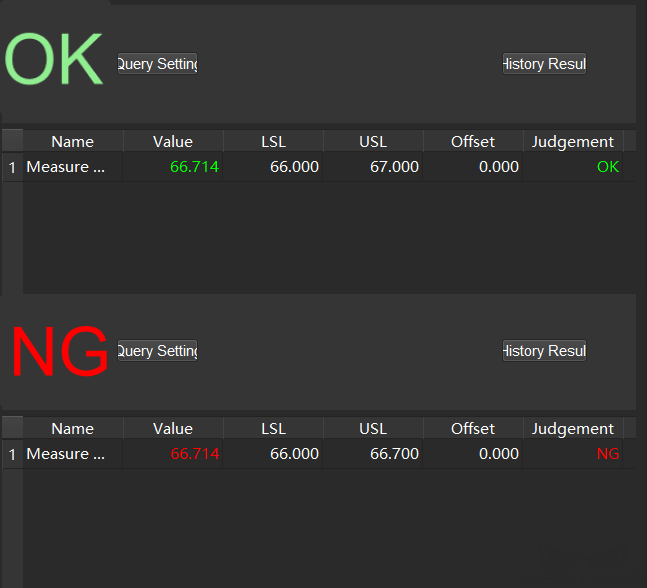
-
Operator Interface:
Click Operator Interface (Custom) in the toolbar to open the Operator Interface. If you need a custom development of this interface, please contact Mech-Mind Technical Support.
Now you have completed your first application using Measurement Mode!
General Workflow in Measurement Mode
By completing the first application, the general workflow in measurement mode can be summarized as follows.
-
Create a New Project and switch to measurement mode.
-
Connect the Steps to program and configure parameters in Steps. The main algorithms in measurement mode will be introduced in the next section.
-
Select an ROI and add base points or detect points in the sketchpad area.
-
Open the Result View, select the output Step and set the LSL and USL.
-
Check the real-time product image, measurement and statistics in the custom operator interface.