Compatibility Mode Introduction
In compatibility mode, the following situation exists for some robots: when the pose of the real robot is synchronized with that of the simulated robot in the software simulation area, the robot tool pose displayed on the teach pendant does not match the tool pose in the software interface. The problem occurs in the robots including all FANUC and YASKAWA four/five/six-axis robots, six-axis robots of Kawasaki R series, all STAUBLI six-axis robots, and all AUBO and HANS robots.
In compatibility mode, when software communicates with the robot through Standard Interface or Master-Control, the difference in the tool pose will be compensated automatically. However, when you perform manual calibration, teach the pick point, or send the planning or recognition result in tool poses to the robot through Adapter, the difference in the tool pose should be compensated manually.
Scenarios Require Manual Compensation
| If the robot you use belongs to FANUC four/five/six-axis robots, YASKAWA four/five/six-axis robots, Kawasaki R series six-axis robots, STAUBLI six-axis robots, AUBO, or HANS robots, you need to manually compensate the difference when you perform manual calibration, teach the pick point, and establish Adapter communication. |
Manual Calibration
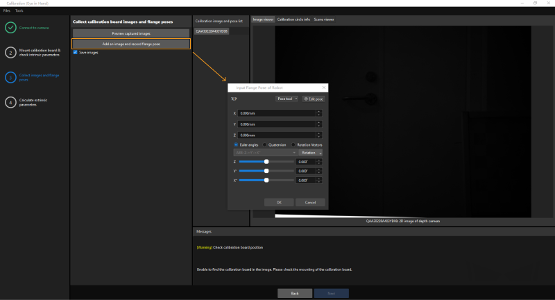
In the process of manual calibration, click Collect images and flange poses, and then enter the flange pose data in the Input Flange Pose of Robot window.
The compensation value should be added to the Z-value of the tool pose displayed on the teach pendant, and then the result can be used as the Z parameter in the software.
Teach the Pick Point
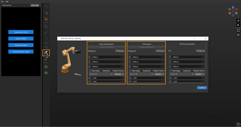
When adding pick point by teaching in the Matching Model and Pick Point Editor, the image capturing pose and picking pose should be entered in the form of robot flange poses.
The compensation value should be added to the Z-value of the tool pose displayed on the teach pendant, and then the result can be used as the Z parameter in the software.
How to Determine Compensation Value
You can determine compensation value through the following methods:
-
Synchronize the real robot with the simulated robot in the software simulation area. The compensation value is the difference of Z values between the robot tool pose displayed on the teach pendant and in the software.
Take the robot in the following table as an example.
|
|
The tool pose displayed on the teach pendant |
The tool pose displayed in Mech-Viz |
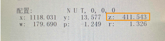
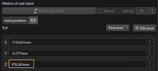
The Z values of tool pose displayed on the teach pendant and Mech-Viz are respectively 411.543, and 976.543, so the compensation value is 976.543 - 411.543 = 565 mm.
-
Check the parameter document of the robot. The compensation value is the value of the first DH parameter (DH1), or the value of Zoffset in the parameter document.
Take the robot in the following table as an example.
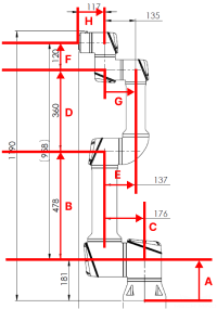
From the UR_16E_algo.json file, we know that DH1 corresponds to A. By checking the DH specifications, we know that A equals 181 mm, so the compensation value is 181 mm.
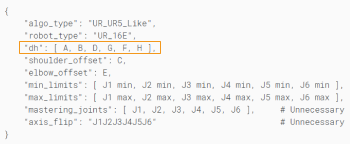
UR_16E_algo.json
DH Specification