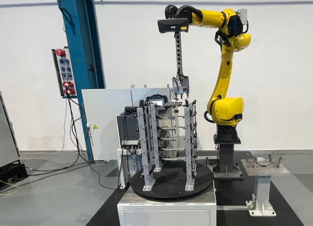
EIH System Drift Auto-Correction
This chapter will introduce the function, applicable scenarios, and deployment process of the “EIH System Drift Auto-Correction” feature.
|
System drift refers to the accuracy drift of the vision system, where the accuracy of the vision system gradually decreases over time. This is typically caused by factors such as changes in the external environment and internal instability of the vision system. |
Function
During the operation of the vision system, the following problems impact system stability and later maintenance costs.
-
Large temperature differences between day and night on-site may lead to fluctuations in picking accuracy.
-
Long-term operation of the vision system may result in a deterioration of picking accuracy.
To address the mentioned problems by correcting the system drift automatically, the “EIH System Drift Auto-Correction” feature is built into the Accuracy Error Analysis Tool for vision systems in the Eye in Hand setup.
Applicable Scenarios
The “EIH System Drift Auto-Correction” feature applies to the following scenarios.
-
The scenario where the camera is mounted in the Eye in Hand method.
-
The scenario where there is a high-level requirement for long-term stability of vision system.
Deployment Process
|
The deployment process for this feature is limited to use in China only. If deployment is needed for projects in other regions, please contact Mech-Mind product engineer. |
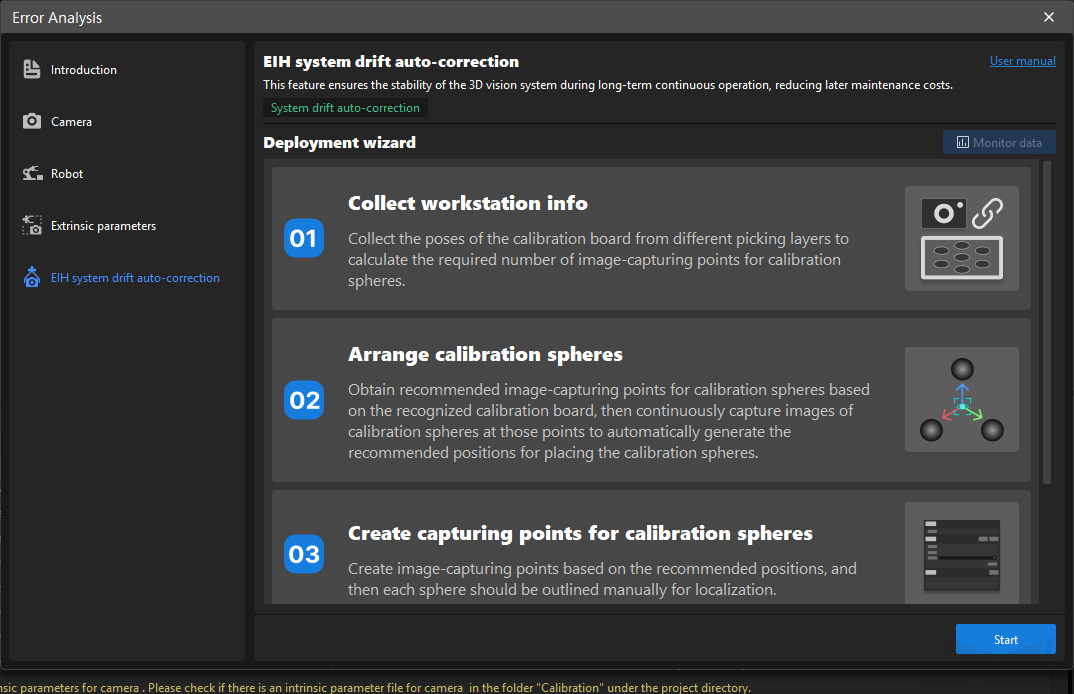
The deployment process of this feature is shown below.
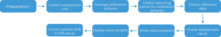
-
Preparation: Before deployment, it is necessary to check the robot’s repeatability to ensure normal operation, and then prepare the calibration board and calibration spheres as required.
-
Collect workstation info: Collect the poses of the calibration board from different picking layers to calculate the required number of image-capturing points for calibration spheres.
-
Arrange calibration spheres: Obtain recommended image-capturing points for calibration spheres based on the recognized calibration board, then continuously capture images of calibration spheres at those points to automatically generate the recommended positions for placing the calibration spheres.
-
Create capturing points for calibration spheres: Create image-capturing points based on the recommended positions, and then each sphere should be outlined manually for localization.
-
Collect reference data: Collect the poses of calibration spheres, and calculate the repeatability of the calibration sphere poses for system drift correction.
-
Check deployment result: Check the recommended image-capturing points and other information after the above deployment.
-
Write robot program: The robot program is written to control the robot during actual production to collect calibration sphere poses, which will be used as field data for system drift correction.
-
Deploy vision project: Add the “Correct EIH System Drift” Procedure to correct the system drift automatically.
-
Correct system drift in EIH setup: After completing the above deployments, the system drift will be corrected automatically during the actual production process.
Preparation
Before deployment, it is necessary to complete a number of preparation tasks. The detailed description is as follows.
Check Robot Repeatability
To ensure a normal repeatability of the robot in the process of deployment, it is necessary to check the robot repeatability before deployment. For detailed instructions, please refer to Check Robot Repeatability.
Prepare Calibration Board
The calibration boards of all CGB and BDB models are supported. Please contact the Mech-Mind engineers to obtain them.
Prepare Calibration Sphere
Three calibration spheres will be used in the process of drift correction. You can follow the requirements below to prepare them.
-
Use the calibration spheres provided by the Mech-Mind
Mech-Mind provides matte iron spheres with diameters of 60 mm. Please contact the Mech-Mind engineers to obtain them.
Mech-Mind only provides calibration spheres. Other accessories need to be prepared by yourself. For specific introductions of calibration spheres and other accessories, please refer to Calibration Sphere.
-
Prepare calibration spheres by yourself
If you want to use other calibration spheres, please ensure the spheres can meet the requirements below.
Material Diameter Sphericity Spherical integrity Their point clouds are in good quality. You can choose matte icon spheres, ceramic spheres, and so on.
-
If the distance from the calibration sphere to the camera is between 0.5m to 2m, a calibration sphere with a diameter of approximately 60mm can be chosen.
-
(Uncommon) If the distance from the calibration sphere to the camera is less than 0.5m, a calibration sphere with a diameter of approximately 30mm or 40mm can be chosen.
-
(Uncommon) If the distance from the calibration sphere to the camera is greater than 2m, a calibration sphere with a diameter of approximately 100mm can be chosen.
As the sphericity needs to be close to 1, the elliptical spheres cannot be used.
A part of the ball can be cut off to form a flat surface for easier installation, but at least four-fifths of the ball’s integrity must be ensured.
-
After completing the preparation, click the Start button in the lower-right corner of the home page to enter the deployment wizard.
|
Collect Workstation Info
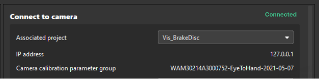
Connect to Camera
-
Associate the project.
Select a project under the currently opened solution, and then the camera information in the project will be obtained automatically.
-
Obtain the IP address and camera calibration parameter group automatically.
When the camera is connected successfully, this feature can obtain the IP address and camera calibration parameter group automatically.
Set Camera Parameter Group
When the camera is connected, it is necessary to select the camera parameter group in the dropdown menu in the “Camera parameter group.”
Confirm On-Site Situation
After completing the relevant settings of the camera, you need to select whether to arrange the calibration spheres according to on-site situation.
Locate Calibration Board
After completing the above steps, please locate the calibration board according to the illustration and requirements below and collect the calibration board poses from each picking layer in the workstation.
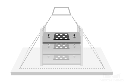
|
To ensure accurate calibration board localization, it is necessary to ensure that there is only one calibration board in the camera’s field of view. |
-
Place the calibration board in the center of the field of view at the height where the top layer of target objects is located.
For large workpieces, the calibration board should be placed on the specific features of the workpiece, namely the areas used for point cloud model matching.
-
Move the robot to the image-capturing point above the picking layer. This image-capturing point must be the same as the one used in the actual production process.
-
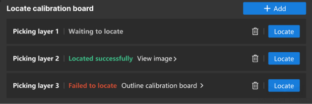
Click the + Add to add a new picking layer.
-
Click Locate to capture an image of the calibration board for the current picking layer.
-
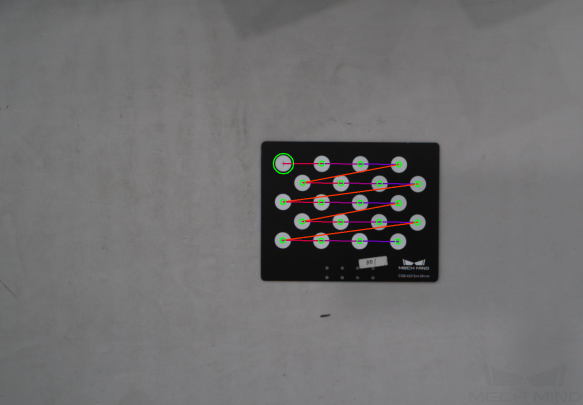
If the localization succeeds, the message Located successfully will occur. Click View image to check the successfully located calibration board, which is as follows.
-
If the localization fails, the message Failed to locate will occur. You can click Outline calibration board to outline the calibration board in the pop-up window, or try again after adjusting the camera parameter group.
-
-
Repeat the above steps until information for all picking layers is collected.
When the workstation info is collected, click Nextto arrange calibration spheres.
Arrange Calibration Spheres
By locating the calibration board and recording the robot flange pose, obtain the robot pose for capturing the calibration spheres. After capturing the image at this pose, you can obtain the recommended positions for the calibration spheres, and then fasten the calibration spheres in place.
Arrange Calibration Board
-
Arrange calibration board.
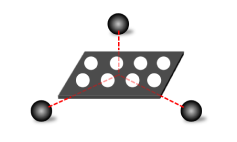
The calibration board should be placed with the front side facing upward, horizontally on the ground, and there should be space around the edges of the calibration board to accommodate the placement of calibration spheres. Typically, a supportive object, such as a wooden board, is needed beneath the calibration board to ensure that the height of the calibration board is consistent with the height of the calibration sphere’s center.
-
Locate calibration board.
Move the robot to bring the camera to an appropriate height, ensuring that the calibration board is clearly visible within the camera’s field of view and at the center of the field of view, and then click Locate.
-
After the localization succeeds, the message Located successfully will occur on the left side of the Locate button, and the image of calibration board will be displayed. At this time, the current robot flange pose should be entered into the frames on the interface.
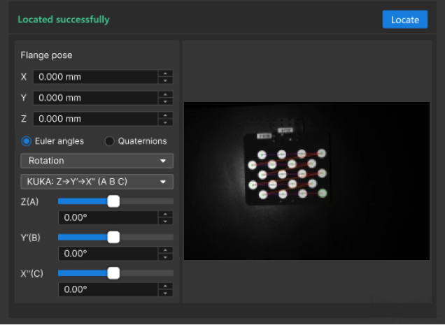
It is necessary to check the Euler angle convention, ensuring the selection is right.
-
If the localization fails, the message Failed to locate will occur on the left side of the Locate button. You can click Outline calibration board to outline the calibration board in the pop-up window.
-
-
Calculate the image-capturing points.
When the calibration board is located successfully, click Calculate image-capturing points to automatically calculate the image-capturing points, i.e. the robot flange poses in the process of image capturing.
Arrange Calibration Spheres
|
If the calibration sphere is arranged according to the on-site situation during the “Collect Workstation Info” step, you only need to set the diameter of the calibration sphere in this step. |
-
Learn about the note of calibration sphere arrangement.
After moving the robot to the recommended pose for image capturing, the plane where the calibration sphere is located should be as perpendicular as possible to the camera optical axis.
-
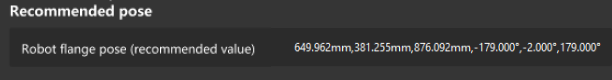
Check recommended robot flange pose.
After a number of robot flange poses are obtained in the “Arrange Calibration Board” step, the nearest robot flange pose to the calibration board will be displayed on the current page as the recommended value. The robot should be moved to the recommended pose.
Please ensure that no collisions occur during the robot’s movement to this pose. It is recommended to jog the robot to the target pose at a low speed and observe whether there will be any collisions.
If there is a possibility of collision in the robot path, the image-capturing point can be lifted appropriately, but it is necessary to ensure that the image-capturing point is lifted within 100 mm. If the lifting distance exceeds 100 mm, a supportive base should be added beneath the calibration sphere.
-
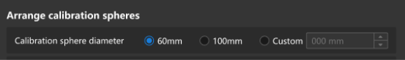
Select the diameter of calibration sphere.
Select the diameter of the calibration sphere in line with the actual calibration sphere.
-
Place and fasten the calibration sphere.
Click Capture continuously, and then arrange and fasten the calibration sphere in the recommended positions (in the green dots).
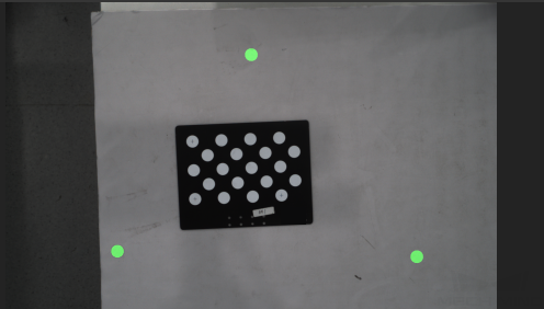
-
Fasten the calibration spheres on the ground. During actual production, avoid accidentally touching the calibration spheres.
-
You can use a marker to draw lines between the calibration sphere and its base as a mark to check if there are any changes in the relative positions of the calibration sphere and its base.
-
After you fasten the calibration sphere, click Confirm fastening.
For more requirements related to the installation and maintenance of the calibration sphere, please refer to Calibration Spheres Installation and Maintenance.
-
When the calibration sphere is fastened, click Next to create image-capturing points for calibration spheres.
Create Capturing Points for Calibration Spheres
Save Image-Capturing Points
The relevant information to the image-capturing points will be saved in the displayed path.
Edit Image-Capturing Points
The recommended image-capturing point is displayed by default currently. To add new image-capturing point, please click +Add; to delete the point, please click ![]() .
.
-
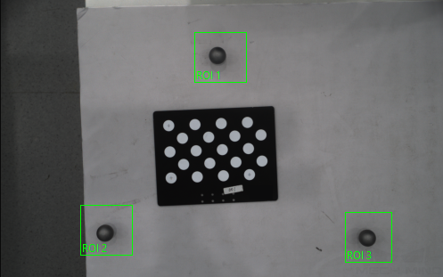
For default image-capturing point, it is necessary to move the robot to the image-capturing point, and then click Outline to outline the calibration sphere for each point.
Please ensure that no collisions occur during the robot’s movement to this pose. It is recommended to jog the robot to the target pose at a low speed and observe whether there will be any collisions.
If there is a possibility of collision in the robot path, the image-capturing point can be lifted appropriately, but it is necessary to ensure that the image-capturing point is lifted within 100 mm. If the lifting distance exceeds 100 mm, a supportive base should be added beneath the calibration sphere.
The frame should completely cover the calibration sphere, leaving a margin of one calibration sphere diameter in each direction (up, down, left, and right) around the calibration sphere. If the message “Failed to locate” appears after outlining the calibration sphere, try expanding the frame range appropriately and reselect the calibration sphere.
-
For the newly added custom image-capturing point, please click
 , and then enter the robot flange pose.
When the image-capturing point of calibration sphere is created, click Next to collect reference data.
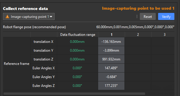
Collect Reference Data
In the dropdown menu on the top, select the image-capturing point, then move the robot to the robot flange pose corresponding to the chosen point. Finally, click Verify on the upper-right corner to verify each image-capturing point, and calculate the repeatability of the calibration sphere pose.
|
Now you have completed the setup of the deployment wizard, and you can click Save to save the deployed content.
When the deployed content is saved, the drift correction project will be created automatically in the Mech-Vision project list to correct the drift problem of vision system in the EIH setup. (Each image-capturing point corresponds to a drift correction project.)
Check Deployment Result
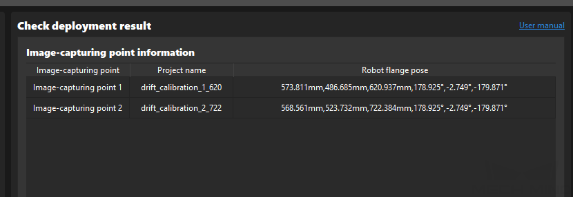
Once you complete the deployment process and save the configuration, you can click Check deployment at the bottom to check the result.
As shown in the figure below, the image-capturing points, project name, and robot flange pose are displayed in the deployment result panel.
Write Robot Program
In the actual production process, it is necessary to write a robot program to make the robot move to the corresponding image-capturing points periodically. Then the robot can carry the camera to capture images of the calibration spheres, collect the poses of the calibration spheres, and generate calibration data for system drift auto-correction according to the reference poses of the calibration spheres.
For the convenience of quickly writing a robot program, taking Kawasaki robots as an example, a example robot program is provided as follows.
Taking two image-capturing points as an example, after running this example program, the robot will move to the corresponding image-capturing points. Then the program will trigger the Mech-Vision project to run, capture images of the calibration spheres, and collect the poses of the calibration spheres.
.PROGRAM Calib_Move()
    ACCURACY 1 ALWAYS
    SPEED 100 MM/S ALWAYS
    JMOVE STAND_BY
    ;layer 1
    LMOVE CALIB[1]
    BREAK
    CALL MM_START_VIS(1,0,1,.#start_vis)
    TWAIT 3
    ;layer 2
    LMOVE CALIB[2]
    BREAK
    CALL MM_START_VIS(2,0,1,.#start_vis)
    TWAIT 3
    JMOVE STAND_BY
.END
The steps in the example program are explained in the table below.
| No. | Step | Code | Description |
|---|---|---|---|
1 |
Define the program name |
.PROGRAM Calib_Move() |
This step defines the “Calib_Move” program. |
2 |
Set parameters related to robot movement. |
ACCURACY 1 ALWAYS SPEED 100 MM/S ALWAYS |
This step defines a robot movement accuracy of 1 and a movement speed of 100 mm/s. |
3 |
Move to image-capturing point 1 to collect poses of calibration spheres. |
LMOVE CALIB[1] BREAK CALL MM_START_VIS(1,0,1,.#start_vis) TWAIT 3 |
This step moves the robot to image-capturing point 1 and triggers Mech-Vision project 1 to run, capturing the image of the calibration spheres and calculating the calibration sphere poses. |
4 |
Move to image-capturing point 2 to collect poses of calibration spheres. |
LMOVE CALIB[2] ;move to calib point #2 BREAK CALL MM_START_VIS(2,0,1,.#start_vis) TWAIT 3 |
This step moves the robot to image-capturing point 2 and triggers Mech-Vision project 2 to run, capturing the image of the calibration spheres and calculating the calibration sphere poses. |
Deploy Vision Project
After writing the robot program, you need to deploy the vision project to correct the system drift during the actual production process. See the following for details.
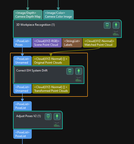
Add the “Correct EIH System Drift” Procedure to the vision project. A “3D Workpiece Recognition” Step or other matching Steps are usually connected before the “Correct EIH System Drift” Procedure to input poses and point clouds, and a Step for pose adjustment usually follows this Procedure.
|
Connecting the input port of the “Correct EIH System Drift” Procedure with the matching Steps is not a must. Instead, the input port that receives the point cloud can connect with any port that outputs the scene point cloud in the camera reference frame. |
Now you have completed the deployment process. The system drift will be corrected automatically when the EIH vision system runs.
Correct system drift in EIH setup
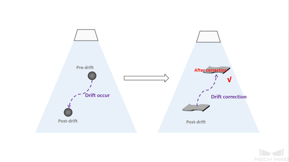
After the above deployment, the “Correct EIH System Drift” Procedure will read the generated data, correct the system drift, and output accurate pick points.
As shown in the figure below, the left figure shows that the camera collects the poses of the calibration sphere before and after the drift, which is used to generate the calibration data. The right figure shows the “Correct EIH System Drift” Procedure to correct the system drift based on the calibration data.
Monitor Data
After the deployment, you can also monitor the system drift in the actual production process.
Click the Monitor data button on the upper-right corner of the “EIH System Drift Auto-Correction” feature home page to enter into the data monitoring dashboard. You can check the datasheet on the dashboard.
The data in white indicates the system drift value within normal range, while the data in red indicates the system drift value that exceeds the alert threshold.
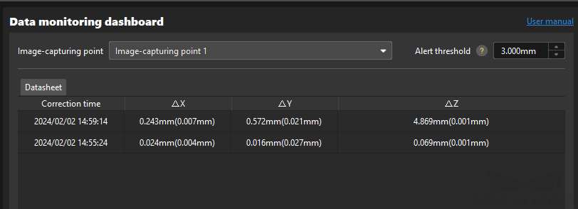
|
A description of the data in the datasheet:
|
|
If the system drift value exceeds the set alert threshold, the auto-correction performance will be affected. It is necessary to check the camera intrinsic parameters, robot repeatability, and camera extrinsic parameters for potential problems, or follow the deployment wizard to collect the reference data again. |