Calibration Spheres
The calibration sphere is usually used in the system drift auto-correction tool. This chapter mainly introduces the selection, installation and maintenance of the calibration spheres.
Select Calibration Spheres
When selecting the calibration spheres, you can use the calibration sphere provided by Mech-Mind (recommended), or you can also prepare the calibration spheres by yourself. The specific description is as follows.
Use the Calibration Spheres Provided By Mech-Mind
It is recommended to use calibration spheres provided by Mech-Mind. See the table below for detailed descriptions.
| Specification | Illustration | Note |
|---|---|---|
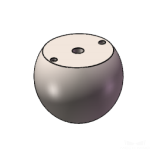
Calibration Sphere (quantity: 3)
|
|
- |
Prepare Calibration Spheres by Yourself
If you prepare the calibration sphere by yourself, the calibration spheres should meet the following requirements in addition to those shown in the table above.
| Material | Diameter | Sphericity | Spherical integrity |
|---|---|---|---|
Their point clouds are in good quality. You can choose matte icon spheres, ceramic spheres, and so on. |
|
As the sphericity needs to be close to 1, the elliptical spheres cannot be used. |
A part of the ball can be cut off to form a flat surface for easier installation, but at least four-fifths of the ball’s integrity must be ensured. |
Select Bolts and Dowel Pins
Mech-Mind does not provide bolts. You need to prepare suitable bolts and dowel pins according to the actual situation.
| No. | Specification | Illustration | Note |
|---|---|---|---|
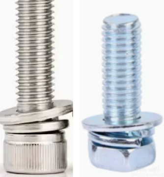
1 |
Class 12.9 M8 bolt kit×3
|
|
Used in conjunction with the threaded hole at the center of the calibration sphere. |
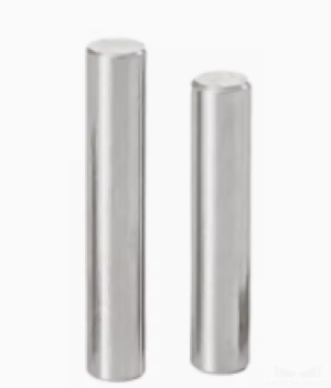
2 |
φ6 cylindrical dowel pin (M6) × 6
|
|
Used in conjunction with the pin holes on both sides of the calibration sphere. |
Mount Calibration Spheres
Ensure an Accurate Installation Position of Calibration Spheres
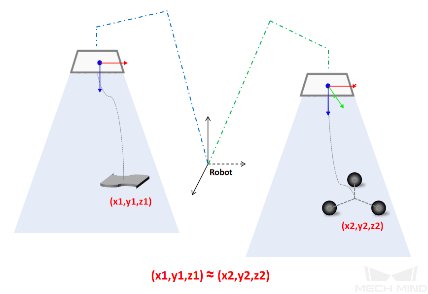
When “EIH System Drift Auto-Correction” tool deployment process is completed, the image-capturing position of calibration spheres will be automatically generated. It is necessary to ensure that the position of calibration sphere is consistent or close to the position of the workpiece in the camera’s field of view in the process of image-capturing.
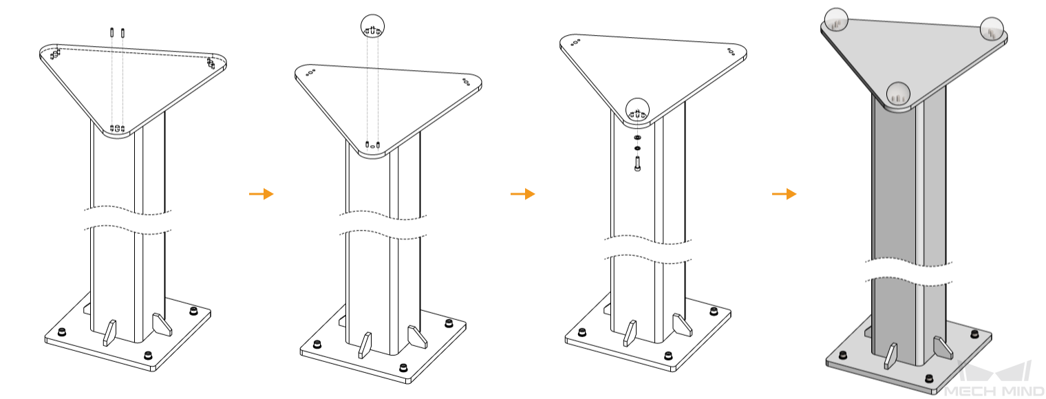
The installation process of the calibration sphere is shown below.
Ensure a Fixed Installation of Calibration Spheres
After the calibration sphere is installed, it is necessary to ensure that it remains firmly in place for an extended period without loosening. The specific requirements are as follows.
-
For scenarios where washers cannot be installed, it is essential to apply adhesive to the bolts.
-
Adhesive selection: It is recommended to use Loctite 243 adhesive.
-
Adhesive application location: At the threaded fastening position.
-
Adhesive quantity control: The adhesive must not overflow the threaded groove, and there should be no adhesive dripping when picking up the bolt after application.
-
-
Requirements for tightening bolts:
-
Recommended length of the wrench: 120 mm
-
Recommended force for tightening bolts: 38–51 N
-
-
When using bolts to secure the calibration sphere, ensure that the length of the bolt exceeding the nut is approximately 0.3 times the diameter of the bolt.
-
It is preferable not to install the calibration sphere directly on the ground. Instead, use a foundation with multiple perforated bolts or pins to securely fasten it to the ground.
-
After installing the calibration sphere, please mark the bolts and pins on the contact surfaces with a marker pen for subsequent inspections to check for any loosening of the calibration sphere.
-
If the calibration sphere is prone to collisions or there are airborne debris (dust, welding spatter, etc.) in the production environment, a protective cover should be added to the calibration sphere.
Ensure No Collision of Grippers at Image-Capturing Position
When the robot carries a large or long gripper to the image-capturing position of the calibration sphere, special attention should be paid to avoiding collisions between the gripper and objects around the calibration sphere. The specific requirements are as follows.
-
If there is a risk of collision between the gripper and objects on the side of the calibration sphere, the calibration sphere should be moved to a more spacious place.
-
If there is a risk of collision between the gripper and objects under the calibration sphere, the calibration sphere should be raised by lifting the foundation of it.
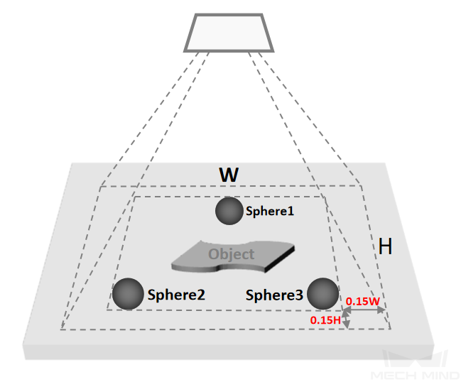
Ensure Proper Distribution of Calibration Spheres
In the “EIH System Drift Auto-Correction” tool deployment process, the recommended installation position of the calibration spheres in the camera’s field of view will be generated. Please ensure that the calibration spheres are distributed properly. The specific requirements are as follows.
-
The calibration spheres are arranged in an isosceles triangle distribution.
-
The area formed by the circumscribed rectangle of the three calibration spheres to the boundary of camera’s field of view occupies approximately 15% of the full field of view.
-
If the size of the workpiece is small, the spacing between the three calibration spheres can be reduced appropriately.
Maintain Calibration Spheres
After the installation of the calibration spheres, it is necessary to maintain them. The specific requirements are as follows.
-
Please regularly check if the calibration spheres are loose. If loosening occurs, it is necessary to redeploy them.
-
Please regularly inspect the surface of the calibration spheres for debris. If debris is present, please use compressed air to blow it away instead of wiping forcefully.