Output
Function
This Step sends the vision result of the current project to the Mech-Viz or communication component for subsequent picking.
|
Only one “Output” Step can be added in a vision project, which means that each vision project contains exactly one “Output” step. |
Usage Scenario
This Step is usually used to send various vision results from the current project to other services.
Input and Output
As a result-output Step in a project, this Step has no output ports and only input ports. It provides four output types: Vision results for picking, Vision results for trajectory, Robot path for picking, and Custom. Different output types correspond to different input ports.
|
All default ports must be connected to valid input data; otherwise, an error will occur when running the "Output" Step. |
The output types and descriptions are as follows.
| Output Type | Description |
|---|---|
Vision results for picking |
Output recognition results related to target object positioning and picking, for subsequent execution of picking tasks by the robot. |
Vision results for trajectory |
Output trajectory results generated along the surface or edges of a target object, for subsequent execution of trajectory tasks by the robot. |
Robot path for picking |
Output the robot path planned by the "Path Planning" Step. |
Custom |
Customize input ports as needed and send specified data. |
The table below uses the “Vision results for picking” port type as an example.
| Input port | Data type | Description |
|---|---|---|
Pick Points |
Pose[] |
List of pick points of the target objects. |
Pick Point Info |
JsonValue |
Pick point related information, including target object names, pick point names, and pick point labels. |
Point Cloud |
PointCloud[] |
Point cloud sent to Mech-Viz. |
Pick Point Labels |
String[] |
Labels for pick points set in the target object editor, typically used for Standard Interface communication with the host computer. |
Target Object Dimensions |
Size3D[] |
The dimensions of the target object. |
Pick Point Offset |
Pose[] |
The offset of the pick point on the target object relative to the object center point. |
Scene Object Names |
String[] |
List of scene object names. The dimensions and poses of objects in this list will be updated. |
Scene Object Dimensions |
Size3D[] |
List of scene object dimensions. Scene object dimensions will be updated in list order. |
Scene Object Poses |
Pose[] |
List of scene object poses. Scene object poses will be updated in list order. |
Custom Ports |
Abstract[]n |
Input port data generated dynamically according to the "Customized Ports Name" parameter. |
|
When the target object is saved by using the "No point cloud model required" workflow in the target object editor, the output pick point will be the same as the input pick point. |
Parameter Description
Output Type Settings
| Parameter | Description |
|---|---|
Output Type |
Description: Select the output type of the Step based on the required vision result. Value list: Vision results for picking, Vision results for trajectory, Robot path for picking, Custom
Default value: Vision results for picking Instruction: Select the output type according to actual requirements. |
Vision results for picking
This output type is suitable for Master-Control, Standard Interface, or Adapter communication.
Mech-Viz can receive the vision results output from this type of port under different communication modes, with only the communication logic differing:
-
When the Master-Control communication mode is used, the vision system sends the vision result to the robot.
-
When the Standard Interface or Adapter communication mode is used, the external device (robot, PLC or host computer) sends commands to the vision system, and the vision system returns the vision result to the external device.
Usage Scenario
| Parameter | Description |
|---|---|
Select Scenario |
Description: Select the usage scenario of the current solution. Value list: 3D model matching (Machine Tending/Positioning/Assembly), Depalletizing and others Instruction:
Default value: 3D model matching (Machine Tending/Positioning/Assembly) |
Method to Convert Data |
Description: By selecting the result conversion method, this Step converts the recognition result to the data type needed for picking. Value list: Generate picking strategy based on object center point, Generate picking strategy based on pick points
Default value: Generate picking strategy based on object center point |
Target Object without Point Cloud Model |
Description: Select a target object that does not require a point cloud model, and this Step can output pick point information for the target object. Please set this parameter when the usage scenario is “Depalletizing and Others”. |
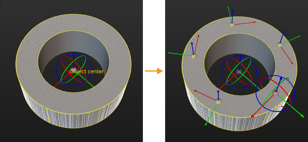
Collision Detection Settings
| Parameter | Description |
|---|---|
Output Point Clouds |
Description: This parameter is used to output the point cloud to the Mech-Viz for collision detection.
|
Point Cloud in Camera Frame |
Description: Please select this parameter when the point cloud is in the camera reference frame. Once this option is selected, the point cloud will be converted to the robot reference frame and sent to Mech-Viz. If this option is not selected, the point cloud will be sent to Mech-Viz directly.
|
Remove Point Cloud of Irregular Shape |
Description: Once this option is enabled, any point cloud overlapping with the collision model of the target object with a non-standard 3D shape will be removed by Mech-Vision to prevent interference in collision detection. Please set this parameter when the usage scenario is “Matching (Machine Tending/Positioning/Assembly).”
|
Search Radius of Target Object Point Cloud |
Description: Take any point in the point cloud of the target object as the center, and the point cloud within the search radius will be removed. Please set this parameter when Remove Point Cloud of Irregular Shape is selected.
|
Other Ports
| Parameter | Description |
|---|---|
Pick Point Labels |
Description: When selected, a "Pick Point Labels" input port is added.
|
Target Object Dimensions |
Description: When selected, a "Target Object Dimensions" input port is added.
|
Pick Point Offset |
Description: When selected, a "Pick Point Offset" input port is added.
|
Update Scene Object |
Description: This parameter is usually used in scenarios where the bin pose needs to be updated dynamically. Once selected, the "Scene Object Names," "Scene Object Dimensions," and "Scene Object Poses" input ports will be added to the Step.
|
Customized Ports Name |
Description: This parameter is used to add custom input ports.
|
Accuracy Drift Correction
| Parameter | Description |
|---|---|
Auto-Correct Accuracy Drift in Vision System |
Description: Once this parameter is selected, the accuracy drift of the vision system will be corrected automatically. This parameter will only be displayed after the Auto-correct accuracy drift in EIH/ETH vision system feature is deployed in the Error Analysis Tool.
|
Vision results for trajectory
This output type is suitable for Master-Control, Standard Interface, or Adapter communication.
Mech-Viz can receive the vision results output from this type of port under different communication modes, with only the communication logic differing:
-
When the Master-Control communication mode is used, the vision system sends the vision result to the robot.
-
When the Standard Interface or Adapter communication mode is used, the external device (robot, PLC or host computer) sends commands to the vision system, and the vision system returns the vision result to the external device.
Usage Scenario
| Parameter | Description |
|---|---|
Select Scenario |
Description: Select the usage scenario of the current solution. Value list: Matching, Others Instruction:
Default value: Matching |
Collision Detection Settings
| Parameter | Description |
|---|---|
Output Point Clouds |
Description: This parameter is used to output the point cloud to the Mech-Viz for collision detection.
|
Point Cloud in Camera Frame |
Description: Please select this parameter when the point cloud is in the camera reference frame. Once this option is selected, the point cloud will be converted to the robot reference frame and sent to Mech-Viz. If this option is not selected, the point cloud will be sent to Mech-Viz directly.
|
Other Ports
| Parameter | Description |
|---|---|
Update Scene Object |
Description: This parameter is usually used in scenarios where the bin pose needs to be updated dynamically. Once selected, the "Scene Object Names," "Scene Object Dimensions," and "Scene Object Poses" input ports will be added to the Step.
|
Customized Ports Name |
Description: This parameter is used to add custom input ports.
|
Accuracy Drift Correction
| Parameter | Description |
|---|---|
Auto-Correct Accuracy Drift in Vision System |
Description: Once this parameter is selected, the accuracy drift of the vision system will be corrected automatically. This parameter will only be displayed after the Auto-correct accuracy drift in EIH/ETH vision system feature is deployed in the Error Analysis Tool.
|
Robot path for picking
This output type is suitable for Standard Interface or Adapter communication mode. The external device (robot, PLC or host computer) sends commands to the vision system, and the vision system returns the planned waypoints to the external device.
Once this output type is selected, only the “Path Planning” Step can be used to receive the vision result corresponding to this port type. Receiving vision results via Mech-Viz is not supported.
Custom
This output type is suitable for Adapter communication. The external device (robot, PLC, or host computer) sends commands to the vision system, and the vision system returns configured output data to the external device.
After selecting this output type, data can be communicated using custom communication keys. Data to be output can be configured through the "Customized Ports Name" parameter.
Other Ports
| Parameter | Description |
|---|---|
Customized Ports Name |
Description: This parameter is used to customize the input port.
|
|
Custom data items are ordered alphabetically by custom port name (A-Z). For example, if custom data port names are:
The transmitted data will be sorted alphabetically by custom name as follows: …aData, bData, cData… |