Orthographic Projection Inverse
Usage Scenario
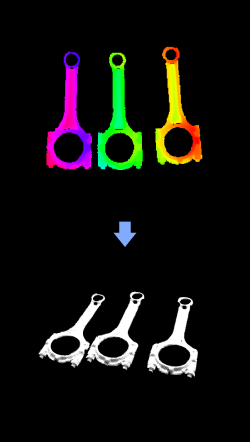
This Step is usually used for measurement scenarios. It usually follows the Orthographic Projection Step to convert the 2D image obtained from orthographic projection into the 3D point cloud.
Input and Output
Input
| Input port | Data type | Description |
|---|---|---|
Point Cloud |
PointCloud/XYZNormal |
Point cloud with normal (to provide reference for inverse orthographic projection). |
Mask |
Image/Color/Mask |
Mask of 2D points for inverse orthographic projection. |
Point Cloud 3D Min Point |
Pose [] |
Minimum value of the three-dimensional coordinates (X, Y, Z) among all points in the point cloud. |
Resolution |
Number |
Resolution refers to the number of pixels per unit length on the 2D image formed by the orthographic projection. The unit length is 1 meter. |
Mask Blank Border Width |
Number |
A blank border will be added to the four sides of the mask of the 2D image formed by projection. |