2D Camera Management
Introduction
The 2D Camera Management tool is used to centrally manage all 2D cameras in the system. It serves as the entry point for device configuration and debugging before image acquisition.
In this tool, you can:
-
Search for and add multiple 2D cameras
-
Manage camera connection status (connect, disconnect, delete, etc.)
-
Configure camera trigger method and connection parameters
-
Adjust image acquisition parameters and preview effects in real time
This tool is primarily used for camera debugging during project preparation. After configuration, the camera can be used by the 2D Smart Camera Step in a project workflow for image acquisition.
Start the Feature
You can open the 2D Camera Management tool in the following ways:
-
In the Step Parameters pane of 2D Smart Camera, click the Camera management button to enter.
-
Select from the menu bar.
User Interface
The 2D Camera Management tool interface consists of the following areas.
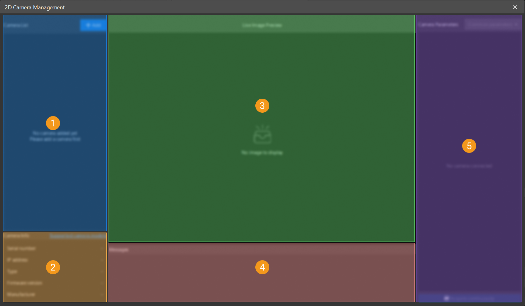
| No. | Area | Description |
|---|---|---|
① |
Camera List |
Displays all added 2D cameras. You can add and connect, disconnect, rename, or delete cameras. |
② |
Camera Info |
Displays the basic information of the selected camera, including serial number, IP address, firmware version, manufacturer, and type. |
③ |
Live Image Preview |
Displays the acquired live images for debugging. |
④ |
Messages |
Displays the camera connection status, trigger information, and error messages. |
⑤ |
Camera Parameters |
Adjusts camera parameters and control image acquisition status. |
How to Use
Connect Camera and Acquire Images
Follow the steps below to connect a camera and acquire images using the 2D Camera Management tool:
-
Add a camera and establish the connection.
In the camera list area, click the Add button, and then add a 2D camera in one of the following ways.
-
Automatic search
The system will automatically scan the current network environment, search for available cameras on the same subnet, and list the search results. Applicable to most standard deployment scenarios.
-
Search by IP address
You can add a device by manually entering its camera IP address.
Once added, the camera is set to connected by default. You can disconnect, rename, or delete a camera in the camera list area, and modify the IP address or upgrade the camera firmware in the Camera Info area.
The camera name can be modified only when the camera is connected. The camera IP address and firmware can be modified only when the camera is disconnected. -
-
Camera IP address.
If this is the first time you connect the camera, or the camera and the IPC are not on the same subnet, modify the camera IP address first.
Obtain the current NIC IP information of the IPC and confirm the target subnet. Then, in the Camera Info area, click the "Modify IP address"
 button, and select the configuration mode based on the on-site network environment.
-
Manual
Select "Manual" and then manually enter the IP address、Subnet mask and Default gateway.
-
Automatic (DHCP)
Select "Automatic (DHCP)" to have the DHCP server automatically assign network parameters. In this mode, the IP address, subnet mask, and default gateway are obtained automatically.
After saving the configuration, reconnect the camera and confirm the connection status is normal. It is recommended to assign a unique IP address to each camera to avoid address conflicts on the same subnet that could cause connection issues.
-
-
Check image acquisition results.
Click Acquire continuously to acquire images and check image acquisition results.
If continuous acquisition is slow, resulting in a long interval between consecutive frames, check the network bandwidth.
-
Adjust camera parameters.
When checking image acquisition results, confirm whether image brightness, clarity, and orientation are correct. If the results do not meet expectations, adjust parameters such as Exposure time and Gain. For detailed parameter descriptions, refer to Camera Parameter Description.
Manually Configure Output Signals
When the Output mode of a camera output signal line is set to Manual control, you need to use the 2D Camera Output Signal Configuration tool to configure the project trigger order and output line settings. For details, refer to 2D Camera Output Signal Configuration.
Camera Parameter Description
Common Parameters
Image Acquisition Settings
| Parameter | Description |
|---|---|
Exposure Time |
Parameter description: Controls the exposure duration for a single frame.
|
Gain |
Parameter description: Amplifies the image signal. Excessive gain amplifies noise. Increase gain only when exposure cannot provide required brightness.
|
Gamma Correction Value |
Parameter description: Adjusts the contrast of the image. |
Built-in Light Settings
| If the 2D camera does not have built-in lights, the Built-In Light Mode and Built-In Light Area parameters will not be displayed. |
| Parameter | Description |
|---|---|
Built-In Light Mode |
Parameter description: Sets the working mode of the built-in lights.
|
Built-In Light Area |
Parameter description: Sets the illumination area of the built-in lights.
|
All Parameters
Trigger and Connection Settings
Used to configure the data acquisition triggering method and connection behavior of the camera.
| Parameter | Description | ||
|---|---|---|---|
Enable Heartbeat Detection |
Parameter description: Once enabled, the system periodically monitors the camera connection status. If connection fails, the system automatically attempts to reconnect.
|
||
Max Reconnection Attempts |
Parameter description: Sets the maximum number of automatic reconnection attempts. Too few attempts may prevent recovery from brief disconnections; too many may extend the waiting time during exceptions. |
||
Data Acquisition Trigger Source |
Parameter description:Sets the trigger method for image acquisition.
|
||
Max Reconnection Attempts |
Parameter description: Sets the maximum number of automatic reconnection attempts. Too few attempts may prevent recovery from brief disconnections; too many may extend the waiting time during exceptions. |
||
Trigger Delay |
Parameter description: Sets the delay time for image acquisition after triggering.
|
||
Trigger Polarity |
Parameter description: hen Data Acquisition Trigger Source is set to Line X, this parameter sets which edge of the signal triggers image acquisition. Options: Rising edge, Falling edge
Adjustment: Select based on the actual trigger signal characteristics. |
||
Max Buffered Frames |
Parameter description: Sets the maximum number of image frames that can be buffered in the camera.
|
||
Buffer Overflow Handling Policy |
Parameter description: This parameter is used to select the solution to the cache overflow. Options: Delete earliest acquired data, Pause current data acquisition
Adjustment: Select an appropriate handling policy based on scenario requirements. |
||
Clear Cache |
Parameter description: Manually clears all image data in the current buffer.
|
||
Output All Buffered Frames |
Parameter description: Outputs all image frames in the current buffer to the specified path for subsequent analysis and debugging.
|
Image Acquisition Settings
Used to configure image quality parameters. After adjusting the parameters, click the Acquire continuously button in the lower-right corner and see the result in the live image preview area. If the image does not meet expectations, click the Stop acquisition button and continue adjusting the parameters until the desired result is achieved.
| Parameter | Description |
|---|---|
Exposure Time |
Parameter description: Controls the exposure duration for a single frame.
|
Gain |
Parameter description: Amplifies the image signal. Excessive gain amplifies noise. Increase gain only when exposure cannot provide required brightness.
|
Gamma Correction Value |
Parameter description: Adjusts the contrast of the image. |
Horizontal flip |
Parameter description: Flips the image horizontally (left-right mirror). |
Vertical flip |
Parameter description: Flips the image vertically (top-bottom mirror). |
Image Width |
Parameter description: Sets the width (in pixels) of the captured image, defined relative to the image center. |
Image Height |
Parameter description: Sets the height (in pixels) of the captured image, defined relative to the image center. |
Image quality |
Parameter description: Sets the imaging quality of the image.
|
Focus Distance |
Parameter description: Adjusts the focus distance of the camera to obtain clear images. |
Enable JPEG Compression |
Parameter description: Enables the JPEG compression function. Once enabled, you need to set the JPEG quality. The acquired images will be compressed in JPEG format to reduce image data size. This is suitable for scenarios with limited network bandwidth. |
Built-in Light Settings
| If the 2D camera does not have built-in lights, the Built-In Light Mode and Built-In Light Area parameters will not be displayed. |
| Parameter | Description |
|---|---|
Built-In Light Mode |
Parameter description: Sets the working mode of the built-in lights.
|
Built-In Light Area |
Parameter description: Sets the illumination area of the built-in lights.
|
I/O Signal Settings
Used to configure the input and output parameters of the camera.
-
Input Signals
Parameter Description Debounce Time
Parameter description: Sets the debounce time for camera input signals to avoid false triggers caused by signal jitter.
-
Output Signals
Parameter Description Output Mode
Parameter description: Sets the output mode of the camera.
Options: Disabled, Active during exposure, Manual control
-
Disabled: The line does not output any signal.
-
Active during exposure: Outputs a valid signal during camera exposure.
-
Manual control: The output timing is controlled by the user or program.
Adjustment: Select an appropriate output mode based on actual requirements. Active during exposure is suitable for scenarios that require synchronized acquisition signals. Manual control is suitable for scenarios that require customized output signal control.
Polarity
Parameter description: Sets the signal level at which the camera output signal is considered "active".
Options: High, Low
Adjustment: Select an appropriate polarity based on actual requirements. High is suitable for scenarios where the output signal should be active at high level. Low is suitable for scenarios where the output signal should be active at low level. -
-
Configurable Signal
The number of configurable output signals varies depending on the camera model.
Parameter Description Line Mode
Parameter description: Sets the mode of the current configurable signal line.
Options: Input, Output
Input: The line functions as an input signal. You can configure Debounce time but cannot configure Output Mode and Polarity.
Output: The line functions as an output signal. You can configure Output Mode and Polarity.Debounce Time
Parameter description: Sets the debounce time for camera input signals to avoid false triggers caused by signal jitter.
Output Mode
Parameter description: Sets the output mode of the camera.
Options: Disabled, Active during exposure, Manual control
-
Disabled: The line does not output any signal.
-
Active during exposure: Outputs a valid signal during camera exposure.
-
Manual control: The output timing is controlled by the user or program.
Adjustment: Select an appropriate output mode based on actual requirements. Active during exposure is suitable for scenarios that require synchronized acquisition signals. Manual control is suitable for scenarios that require customized output signal control.
Polarity
Parameter description: Sets the signal level at which the camera output signal is considered "active".
Options: High, Low
Adjustment: Select an appropriate polarity based on actual requirements. High is suitable for scenarios where the output signal should be active at high level. Low is suitable for scenarios where the output signal should be active at low level. -
Troubleshoot
Any camera cannot be found in the automatic search window
Symptom:
Cameras could not be automatically discovered in the Add Camera window.
Possible Causes:
-
The camera is not on the same subnet as the IPC.
-
The camera is not powered on or the Ethernet cable is disconnected.
-
The camera is occupied by other software.
Solution:
-
Check whether the IP addresses of the camera and the IPC are on the same subnet and adjust the network settings.
-
Confirm that the camera is powered on and make sure that the Ethernet cable is securely connected.
-
Close other software that may occupy the camera. Ensure the camera is idle, then search again.
Connected but no image
Symptom:
The camera is connected, and after clicking the Acquire continuously button, the live image is blank or black.
Possible Causes:
-
The data acquisition trigger source is incorrectly configured.
-
If the data acquisition trigger source is correctly configured, the external signal may not be connected.
-
The exposure time is too short, resulting in black images.
Solution:
-
Make sure the data acquisition trigger source matches the actual acquisition method (software or external).
-
If using external, ensure that the trigger cable is correctly connected and receives a valid signal input.
-
Adjust the exposure time to achieve proper image brightness. If necessary, increase the gain while avoiding excessive noise.
Excessive image noise
Symptom:
Acquired images exhibit significant noise and a grainy appearance, which can affect detection or measurement effect.
Possible Causes:
-
The Gain value is set too high.
-
Insufficient ambient light.
Solution:
-
Increase the intensity of the light source first to enhance the overall image brightness.
-
Increase the exposure time to allow more light to be captured by the sensor.
-
If the issue persists, decrease the Gain setting appropriately.