Set the Pick Points by Jogging the Robot, and Generate the Point Cloud Model Based on the Acquired Point Cloud
In this workflow, you can add the pick point to the target object by robot teaching, and then acquire the point cloud to generate the point cloud model and create the target object.
Under the Jog robot and get point cloud workflow in the target object editor, click Select, and set the target object name to enter the configuration process. The overall configuration process is shown in the figure below.

-
Teach the pick point: Add the pick point to the target object by the robot teaching method.
-
Acquire the point cloud: Use the current project to acquire the point cloud. Then adjust the parameters, set the 3D ROI and remove the background to generate a point cloud model.
-
Edit model: Edit the generated point cloud model, including the calibration of the object center point and configuration of the point cloud model, to ensure better performance of the subsequent 3D matching.
-
Collect data for drift correction: For solutions deployed with the “Auto-correct accuracy drift in vision system” feature, additional drift correction data must be collected to ensure pick points remain accurate and feasible after correction.
-
Set pick point: Set the pick point or add the pick point array on the edited point cloud model.
-
Set collision model (optional): Generate the collision model for collision detection during path planning.
|
When the orientations of incoming target objects are inconsistent, use this process to set pick points for objects in each orientation and generate point cloud models, thereby creating target objects with different orientations. |
The following sections provide detailed instructions on the configuration.
Teach the Pick Point
When teaching pick points, if the target object is inconvenient to move, you can acquire the background depth image before placing the target object. This image will be used to remove background interference during subsequent point cloud processing. This is an optional operation and only applies to this "Jog robot and get point cloud" workflow.
Click here to view the background acquisition process.
-
In the "Teach pick point" parameter panel, click Acquire background to enter the background acquisition process.
-
The “Capture Images from Camera” Step in the current project should be used to acquire the point cloud. If the solution contains multiple projects, there may be multiple “Capture Images from Camera” Steps. Please select the appropriate one based on your actual needs. Then click Acquire background, and then the result can be viewed in the visualization area.
-
After confirming the result, click Save and apply to return to the "Teach pick point" panel and continue teaching.
|
When acquiring the background, note the following:
|
If background acquisition is required, follow the process above. After completing this optional step, place the target object and teach pick points according to the steps below. If background pre-acquisition is not required, proceed directly with the steps below.
-
Place the target object within the camera’s field of view and ensure that the robot can pick the target object properly.
-
Use the teach pendant to control the robot to accurately reach the expected pick point of the target object.
-
Move the TCP of the robot as close as possible to the center of the point cloud model, thus reducing the picking error.
-
Record and enter the robot flange pose and TCP (tool pose relative to the robot flange) at the pick point in the parameter configuration section on the right.
-
Use the teach pendant to control the robot to move away from the pick point, ensuring that the position of the target object remains unchanged during the departure process.
-
Collect the point cloud of the target object and create a point cloud model.
|
When teaching pick points, take note of the following:
|
Acquire Point Cloud
Set Project Information
Select the “Capture Images from Camera” Step in the current project to acquire the point cloud. If the solution contains multiple projects, there may be multiple “Capture Image from Camera” steps. Please select the appropriate one based on your actual needs. Then click Acquire point cloud, and then the result can be viewed in the visualization area.
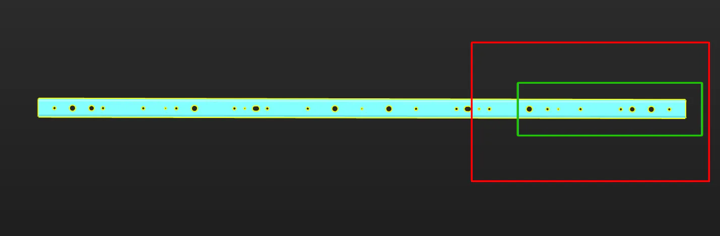
Note that when the camera’s field of view cannot cover the entire target object, priority should be given to ensuring that the key areas of the object are within the camera’s field of view.
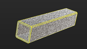
The figure below shows an example of a long sheet metal part. Assuming that the region marked by the red frame on the right is the camera’s FOV, it is recommended to select the point cloud within the region marked by the green frame as the point cloud model for matching stability. Make sure that the region marked by the green frame is within the camera’s FOV when acquiring data. Specifically, the right edge part should be within the camera’s FOV.
Record Robot Flange Pose at Image-Capturing Point
If the camera is mounted in the EIH mode, you can click the Obtain current pose button to obtain the robot flange pose when capturing the point cloud. Please note:
-
The pose refers to the robot flange pose, not the TCP.
-
The pose corresponds to the robot flange pose at the image-capturing point.
-
Carefully check the values to avoid errors.
Preprocess Parameters
To remove interference points and speed up processing in subsequent Steps, you can perform preprocessing on the point cloud. For detailed explanations of the parameters, refer to Preprocessing Parameters.
|
If the “3D Target Object Recognition” Step is used in the project, you can enable Use parameters of Step “3D Target Object Recognition”, and then the parameter values in the “3D Target Object Recognition” Step will be synchronized. This improves the accuracy of 3D matching. |
Set ROI and Remove Background
To quickly remove irrelevant point clouds in the scene and extract the target object point cloud, you can set an ROI and remove the background.
Two methods are supported for background removal:
-
Remove background point cloud only
To remove the background point cloud by using this method, the depth map of background must be acquired and saved in advance in the previous "Teach pick point" step. After acquiring the point cloud, click Remove background only, and the tool automatically removes the background from the current point cloud using the saved background depth image.
-
Acquire and remove background point cloud
If background data was not acquired in advance in the previous "Teach pick point" step, use this method to remove the background by acquiring a background image here. After acquiring the point cloud, move the target object to be modeled out of the camera’s field of view, then click Acquire and remove background. The tool automatically removes the background point cloud.
Now the point cloud acquisition is completed. You can click Next to start editing the generated point cloud model.
Edit Point Cloud Model
The generated point cloud model should be edited for better performance in the subsequent 3D matching.
Edit Point Cloud
Remove Interference Point Cloud
If there are interference points around the point cloud model, you can remove the interference points by editing the point cloud. Refer to Edit Point Cloud for detailed instructions.
Select Feature Point Cloud
-
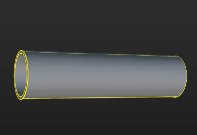
When making the edge point cloud model
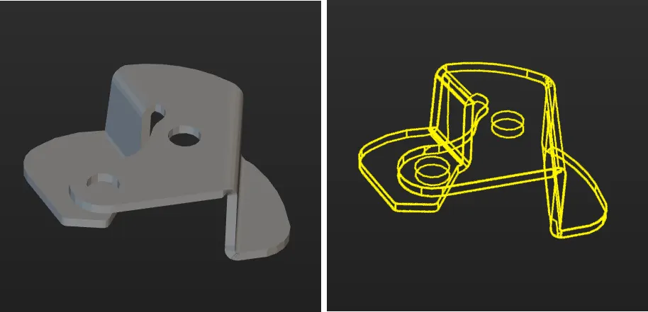
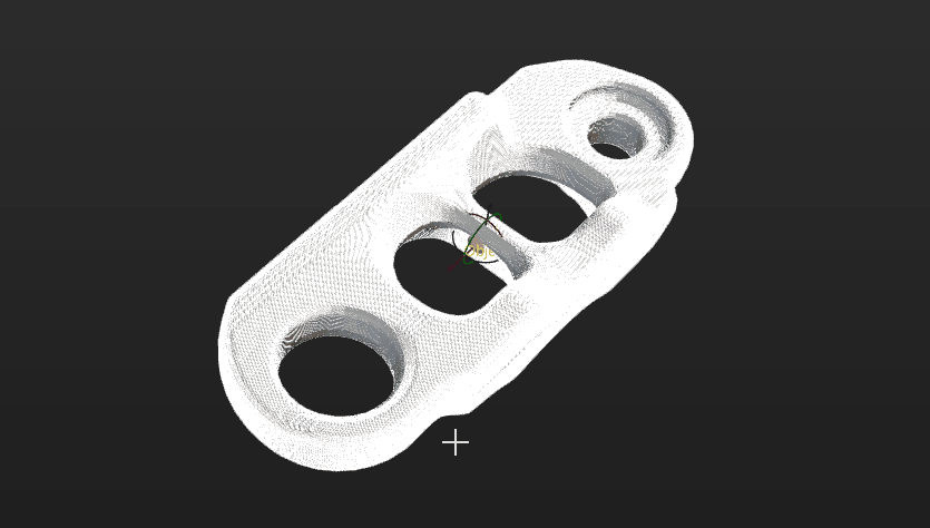
In applications, the target objects usually come in various poses, corresponding to different point clouds. Only the point cloud most representative of the edge feature of the target object should be extracted and retained in the point cloud model.
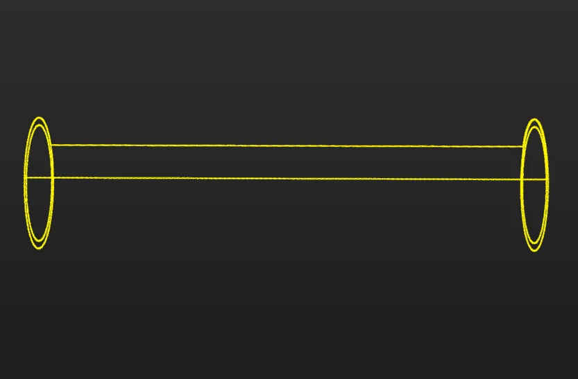
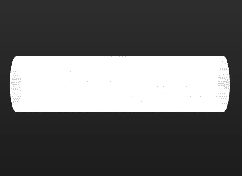
The figure below shows the edge point cloud model of the tube. The tube is symmetrical and similar to a cylinder. On the lateral area of the cylinder, only the point cloud of the edges is retained. Meanwhile, to ensure accurate positioning of the ends of the tube, the point cloud of the edges of the two ends of the tube is retained.
The table below shows the edge point clouds of the tube at different poses.
Tube poses Edge point clouds (in yellow) 

If the target object (such as a sheet metal part) is asymmetrical, the edge point clouds from all viewing angles should be retained.
-
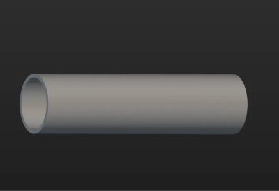
When making the surface point cloud model
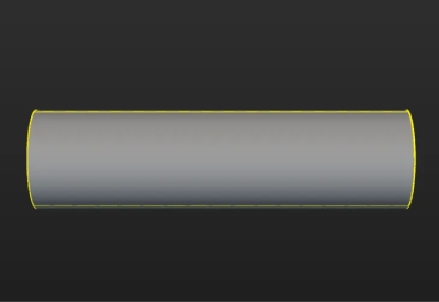
The surface point cloud model is critical in verifying the pose correctness and calculating the pose confidence. Therefore, it is recommended to use the complete surface point cloud of the target object when creating the surface point cloud model to ensure the validity. The figure below shows the surface point cloud model of the tube.
Calibrate Object Center Point
After an object center point is automatically calculated, you can calibrate it based on the actual target object in use. Select a calculation method under Calibrate center point by application, and click Start calculating to calibrate the object center point.
| Method | Description | Operation | Application Scenario |
|---|---|---|---|
Re-calculate by using original center point |
The default calculation method. Calculate the object center point according to the features of the target object and the original object center point. |
Select Re-calculate by using original center point, and click the Start calculating button. |
In general, this method can be used to calculate the center point of all target objects. |
Calibrate to center of symmetry |
Calculate the object center point according to the target object’s symmetry.
|
Select Calibrate to center of symmetry and click the Start calculating button. |
This method can be used to calculate the object center point when filtering matching results by target object symmetry. |
Calibrate to center of feature |
Calculate the object center point according to the selected Feature type and the set 3D ROI. |
|
Target objects with obvious geometric features
|
Reset to Original Point Cloud
During editing, if the current point cloud result is unsatisfactory, click the [Reset button to undo all editing operations and restore the point cloud to its initial state when entering the "Edit model" step.
|
After resetting the point cloud, you need to recalculate the object center point and update the point cloud model configuration. |
Replace Point Cloud Model with STL Model
If the point cloud acquired by the camera is incomplete, you can import an STL model to generate target object point clouds and replace the current camera-acquired point cloud model.
Click Configure STL file, select and import the required STL file, and then enter the configuration process.
Select STL File (Optional)
If you select a wrong STL file or find the normals of the imported STL model are incorrect, click the Select file button to import another STL file.
|
Please refer to STL Model Correction to determine whether the normals of an STL model are correct and how to fix the STL model. |
Set Unit
To fit the generated point cloud model to the actual dimensions of the target object, you need to set the dimensional unit for the STL model to either millimeters (mm) or meters (m), according to actual needs.
Select the Point Cloud Generation Mode
Refer to the table below to select an appropriate point cloud generation mode based on actual requirements.
| Point cloud generation mode | Description | Effect |
|---|---|---|
Generate from entire surface |
The software generates a point cloud according to the entire surface information of the STL model.
|
|
Generate from specified views |
The software will generate point clouds from one or more selected views of the STL model and then stitch them together.
|
|
|
In some scenarios, using the point cloud generated from the entire surface for model matching can yield better results. If the matching result based on the point cloud from a specified view is unsatisfactory, it is recommended to try using the entire surface point cloud instead. |
Set Model Downsampling Method
To ensure the density and uniform distribution of the point cloud and to maintain the matching speed, the point cloud needs to be downsampled before generating a point cloud model. In general, it is recommended to select Automatic downsampling.
If the downsampling result does not meet the requirements, select Custom downsampling and set the Sampling interval based on actual conditions. The larger the Sampling interval, the sparser the downsampled point cloud; the smaller the Sampling interval, the denser the downsampled point cloud.
|
For large target objects (such as air conditioner housings), it is recommended to use Custom downsampling to prevent the loss of some feature point clouds caused by automatic downsampling. |
Generate and Align Point Cloud
After generating the point cloud, align the target object point cloud generated from the STL model with the point cloud actually acquired by the camera to ensure matching accuracy in subsequent steps.
-
Generate the model point cloud.
Click Generate point cloud to generate the point cloud based on the imported STL model.
-
Align the model point cloud with the actual point cloud.
Click Auto-align point clouds to align the model-generated point cloud with the camera-acquired point cloud. If the auto-alignment result is not as expected, you can manually adjust the pose of the point cloud generated from the STL model.
After confirming there is no obvious misalignment between the model point cloud and the actual point cloud, click Save to complete point cloud model replacement.
|
Configure Point Cloud Model
To better use the point cloud model in the subsequent 3D matching and enhance matching accuracy, the tool provides the following two options for configuring the point cloud model. You can enable the Configure point cloud model feature as needed.
Calculate Poses to Filter Matching Result
Once Calculate poses to filter matching result is enabled, more matching attempts will be made based on the settings to obtain matching results with higher confidence. However, more matching attempts will lead to longer processing time.
Two methods are available: Auto-calculate unlikely poses and Configure symmetry manually. In general, Auto-calculate unlikely poses is recommended. See the following for details.
| Method | Description | Operation |
|---|---|---|
Auto-calculate unlikely poses |
Poses that may cause false matches will be calculated automatically. During the calculation process, a set of candidate poses is automatically generated based on equivalent or ambiguous poses that may arise due to the target object’s rotational symmetry about the Z-axis. In subsequent matches, poses that successfully match these poses will be considered unqualified and filtered out. |
Note that the calculation results will not be automatically updated when the point cloud model is modified. If there are any modifications, please click "Calculate unlikely poses" again to update the results. |
Configure symmetry manually |
Calculate potentially mismatched poses based on the manually set parameters such as the Order of symmetry and Angle range. In subsequent matches, poses that successfully match these poses will be considered unqualified and filtered out. |
Select the symmetry axis by referring to Rotational Symmetry of Target Objects, and then set the Order of symmetry and Angle range. |
|
After the symmetry is set manually, the symmetry setting of the target object takes effect in the Coarse Matching, Fine Matching, and Extra Fine Matching (if enabled) processes in the 3D Matching Step. |
|
When this feature is enabled, you should configure the relevant parameters in the subsequent matching Steps to activate the feature. See the following for details.
|
Set Weight Template
During target object recognition, setting a weight template highlights key features of the target object, improving the accuracy of matching results. The weight template is typically used to distinguish target object orientation. The procedures to set a weight template are as follows.
|
A weight template can only be set when the Point cloud display settings is set to Display surface point cloud only. |
-
Click Edit template.
-
In the visualization area, hold and press the right mouse button to select a part of the features on the target object. The selected part, i.e., the weight template, will be assigned more weight in the matching process.
By holding Shift and the right mouse button together, you can set multiple weighted areas in a single point cloud model.
-
Click Apply to complete setting the weight template.
|
For the configured weight template to take effect in the subsequent matching, go to the “Model Settings” parameter of the “3D Matching” Step, and select the model with properly set weight template. Then, go to “Pose Filtering” and enable Consider Weight in Result Verification. The “Consider Weight in Result Verification” parameter will appear after the “Parameter Tuning Level” is set to Expert. |
Make sure you have completed editing the model first.
If the accuracy drift auto-correction feature is not deployed, click the Save button to save the above target object configuration. Or click the Next button to set the collision model.
If the accuracy drift auto-correction feature is deployed, click the Next button to collect data for the drift correction.
Collect Data for Drift Correction
The pick points added by jogging the robot are accurate and reliable. Even when the accuracy drift occurs in the vision system, these pick points will not be affected. In this case, if the drift correction feature in the vision system is enabled, the accuracy of the pick points will be reduced.
If the auto-correction feature has already been deployed, you need to collect data for drift correction after editing the model. The calculated drift compensation will be used for reverse compensation to ensure that the pick points added by jogging the robot remain accurate and feasible.
-
Auto-correct accuracy drift in EIH vision system or auto-correct accuracy drift in ETH vision system.
-
If more than one day has passed since the last drift correction, rerun the robot program to obtain new drift correction data.
-
If the last drift correction was performed within one day, you may skip the correction process and directly click the Start check button.
-
-
Check the program running result.
After running the robot program, click the Start check button to check the running result of the robot program.
If the check passes, it indicates that valid drift correction data has been generated after running the robot auto-correction program.
If the check fails, it indicates that the robot auto-correction program did not generate valid drift correction data. In this case, it is recommended to rerun the robot auto-correction program to capture the calibration sphere poses.
After collecting the drift correction data, click Next to set the pick point.
Set Pick Point
|
After obtaining the pick points through the teaching method, you can skip the step of "set pick point" if no adjustments to the pick points are needed. |
Adjust Pick Point
By default, the pick point list displays the added pick points, defined in the reference frame with the object center point as the origin. Changing the object center point will affect the pick points. You can adjust the default pick points or add new pick points.
-
Adjust default pick points
If the automatically generated pick point does not meet the application requirements, you can customize the values in “Pick point settings” or manually drag the pick point in the visualization area.
-
Add new pick points
If the target object has multiple pick points, click the Add button to add new pick points.
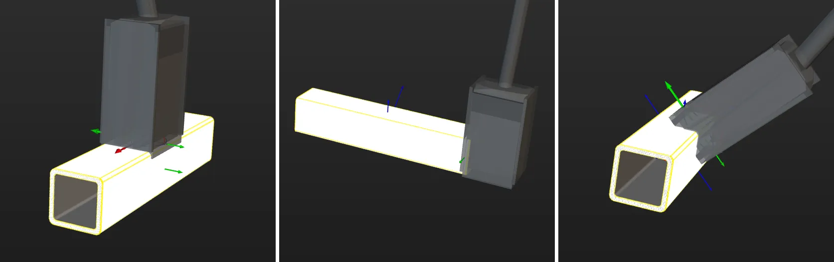
Taking square tubes as an example, the magnetic gripper can pick from the sides, ends, and edges. Therefore, you can add pick points at these positions.
After adding pick points, you can drag the pick points in the pick point list to adjust the priority. The points higher in the list will be considered first during actual picking.
|
If the taught pick point has deviation, you can use the "Compensate pose manually" feature to adjust the current pick point.
|
Set Pick Point Array
When the target object is symmetrical, you can set the pick point array based on the object center point according to actual requirements. Setting the pick point array can prevent the robot’s end tool from unnecessary rotations during picking. This increases the success rate of path planning and reduces the time required for path planning, allowing the robot to move more smoothly and swiftly. The procedures for setting are as follows.
-
Under “Pick point settings,” click Generate next to Pick point array.
-
Refer to Rotational Symmetry of Target Objects to select the axis of symmetry, and then set the Order of symmetry and Angle range.
-
(Optional) Make vision result contain pick point arrays.
If disabled, Mech-Viz or the path planning tool will generate pick point arrays based on the settings in the target object editor and plan the path according to the pick points in the array. If enabled, Mech-Vision will output pick point arrays based on the settings in the target object editor, and Mech-Viz or the path planning tool will use the pick points in the array to plan the path.
-
If you hope pick point arrays can be generated and outputted before path planning, you should enable the option.
-
If you hope pick point arrays can be generated after path planning, you should disable the option.
In real situations, you can decide to enable or not to enable this option based on project requirements and the system performance. For instance, when the pick point array contains many points, it is generally recommended to enable this option to filter out invalid pick points before path planning and output optimized pick point arrays, so as to avoid excessively long path planning times and improve overall efficiency.
-
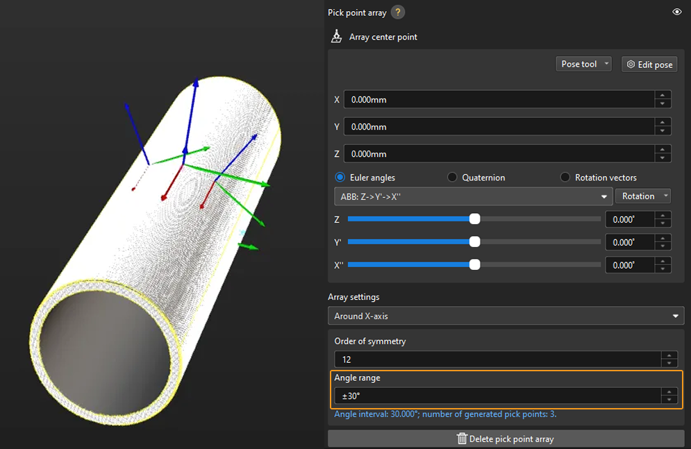
Taking a round tube as an example, the settings of the pick point array are as follows.
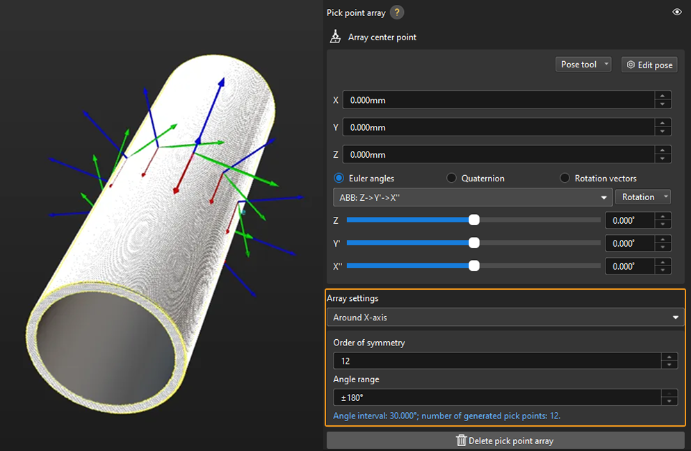
In practice, pick points with a downward Z-axis are often invalid and will affect path planning. Therefore, you should narrow down the Angle range. It is generally recommended to keep the range within ±90°. For example, when configuring a pick point array for randomly placed round tubes, the angle range value is set to ±30° in the figure below.
Add Picking Configuration
Preview Picking Effect
If a tool has been configured in the path planning tool or Mech-Viz, you can enable it in the target object editor to preview the positional relationship between the pick point and the tool during actual picking. This helps determine whether the pick point settings are appropriate. The detailed instructions are as follows.
-
Path Planning Tool
-
Mech-Viz
-
Add an end tool.
Add an end tool and set the TCP in the path planning tool.
-
Preview and enable the tool.
Once the end tool is added, the tool information will be automatically updated in the tool list within the target object editor. You can select a tool from the tool list based on your actual needs and preview the positional relationship between the pick point and the tool in the visualization area during actual picking (as shown in the figure below).
If the tool is modified in the path planning tool, please save the changes in the path planning tool to update the tool list in the target object editor. In addition, enabling the corresponding tool for the pick point in the target object editor is a prerequisite for successful path planning. 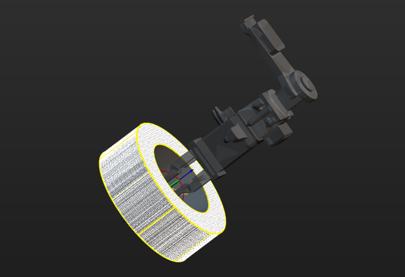
-
Ensure the Mech-Viz project is within the current solution.
To ensure that the end tool information in Mech-Viz can be updated in the target object editor, refer to Export Project to Solution to move the Mech-Viz project to the current solution.
-
Add an end tool.
Add an end tool and set the TCP in Mech-Viz.
-
Preview and enable the tool.
Once the end tool is added, the tool information will be automatically updated in the tool list within the target object editor. You can select a tool from the tool list based on your actual needs and preview the positional relationship between the pick point and the tool in the visualization area during actual picking (as shown in the figure below).
If you have modified the tool configurations in Mech-Viz, save the changes in Mech-Viz to update the tool list in the target object editor. In addition, enabling the corresponding tool for the pick point in the target object editor is a prerequisite for successful simulation in Mech-Viz.
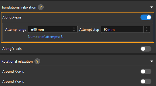
Configure Translational and Rotational Relaxation for Tools
In practice, to ensure the tool can still pick the target object after translating or rotating along a certain axis of the pick point, you can configure the translational relaxation and rotational relaxation for the tool in the target object editor.
Take the round tube as an example, the tool can be translated along the X-axis of the pick point while picking.
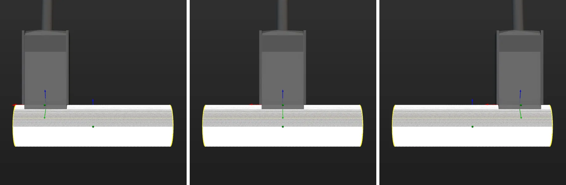
The corresponding configuration is shown below.
Set the Pick Point Selection Strategy
Minimum tool rotation will be used by default, and you can select a pick point selection strategy based on the actual requirements.
-
Minimum tool rotation: When this strategy is selected, the pick point that results in the smallest rotation of the tool’s Z-axis during the entire pick-and-place process will be selected with the highest priority. This strategy can prevent the tool from rotating in vain after picking the target object and avoid dropping the picked target object.
-
Minimum difference between tool and vision pose: When this strategy is selected, the pick point with the smallest angle difference from the target object pose will be selected with the highest priority.
-
Minimum collision between tool and point cloud: When this strategy is selected, the pick point that causes the least collision between the tool and the target object point clouds will be selected with the highest priority.
Click Save to save the configurations for the target object. To set the collision model, click Next.
Set Collision Model (Optional)
The collision model is a 3D virtual object used in collision detection for path planning. You can configure the following settings on the collision model according to the actual situation.
Set Collision Model
The current workflow supports two collision model generating modes. You can select the appropriate mode based on actual requirements. After selection, the tool automatically generates point cloud cubes for collision detection.
| Generating mode | Description | Operation |
|---|---|---|
Use STL model to generate point cloud cube |
Low model accuracy, fast collision detection. |
|
Use point cloud model to generate point cloud cube |
High model accuracy, slow collision detection. |
After selecting this mode, the tool automatically generates a collision model from the current target object’s point cloud model. You can use the "Display collision model" feature to preview the generated collision model. |
Configure Symmetry of Held Target Object
Rotational symmetry is the property of the target object that allows it to coincide with itself after rotating a certain angle around its axis of symmetry. When the “Waypoint type” is “Target object pose”, configuring the rotational symmetry can prevent the robot’s tool from unnecessary rotations while handling the target object. This increases the success rate of path planning and reduces the time required for path planning, allowing the robot to move more smoothly and swiftly.
Select the symmetry axis by referring to Rotational Symmetry of Target Objects, and then set the Order of symmetry and Angle range.
Now, the collision model settings are completed. Click Save to save the target object to Solution folder\resource\workobject_library. Then the target object can be used in subsequent 3D matching Steps.