Advanced Tuning Level Parameter Description
This section introduces the configurable parameters available under the advanced tuning level for the "3D Matching" Step, as well as the description of the functions and tuning recommendations of each parameter.
Input and Output Settings
| Parameter | Description |
|---|---|
Output Type |
Description: This parameter is used to set the information type output by the Step. You can choose to output information about the pick point or the object center point. Value list: Pick point, Object center point
Default value: Pick point |
Input Type |
Description: This parameter is used to set whether to input the point cloud model. Value list: Default, External model
Default value: Default |
Use Inter-frame Difference Recognition
| Parameter | Description |
|---|---|
Use Inter-frame Difference Recognition |
Description: Once this option is enabled, recognition is performed only on regions where the current depth map differs from the previous one, using the previous frame’s recognition results for unchanged areas. This improves recognition efficiency and reduces redundant calculation.
|
Matching Mode
| Matching Mode can only be set when the point cloud model of the selected target object contains both surface and edge point clouds. If the point cloud model contains only one type of point cloud, the corresponding matching mode will be automatically applied in this Step, and manual switching is not allowed. For example, when the point cloud model only contains edge point clouds, the edge matching mode will be used by default, and the parameters related to Matching Mode will be hidden. |
| Parameter | Description |
|---|---|
Auto-Set Matching Mode |
Description: Once this option is enabled, the Coarse Matching Mode and Fine Matching Mode will be automatically set.
|
Coarse/Fine matching mode |
Description: The two parameters are used to set the matching mode. You only need to set them when Auto-set matching mode is not enabled. Value list: Surface matching, Edge matching
Default value: Surface matching Tuning recommendation: To improve matching accuracy, set the Coarse Matching Mode to Edge matching and the Fine Matching Mode to Surface matching. Additionally, this parameter can be adjusted based on the target object features and the quality of the acquired point cloud.
|
Coarse Matching Settings
| Parameter | Description |
|---|---|
Performance Mode |
Description: This parameter is used to set the trade-off between accuracy and speed of matching. The higher the accuracy, the longer the time consumed.
|
Expected Point Count of Model |
Description: This parameter is used to specify the expected number of points in the point cloud model. Set this parameter when Performance mode is Custom.
|
Fine Matching Settings
| Parameter | Description |
|---|---|
Performance Mode |
Description: This parameter is used to set the trade-off between accuracy and speed of matching. The higher the accuracy, the longer the time consumed.
|
Sampling Interval |
Description: The larger the parameter value, the fewer points in the sampled point cloud and the sparser the point cloud. Therefore, the matching is less accurate. The smaller the parameter value, the longer the running time.
|
Max number of iterations |
Description: The larger the value, the higher the matching accuracy, and the slower the processing speed.
|
Standard deviation update step number |
Description: The parameter is used to fine-tune the standard deviation.
|
Deviation Correction Capacity |
Description: This parameter is used to set the intensity of the deviation correction to the matching result from Coarse Matching. The greater the deviation correction capacity is, the more likely the coarsely matched poses can be corrected to the accurately matched poses. Note that an excessive deviation correction capability may lead to a loss of matching accuracy.
|
Extra Fine Matching
| Extra Fine Matching can only be performed when the point cloud model of the selected target object contains both surface and edge point clouds. |
| Parameter | Description |
|---|---|
Enable Extra Fine Matching |
Description: Once enabled, a different mode will be used for fine matching. For example, if the current fine matching mode is surface matching, enabling this feature will perform fine matching again using the edge point cloud model. Once enabled, the final matching accuracy may be improved, but the running time will be slightly increased.
|
Adjust or Filter Poses from Coarse Matching
| Parameter | Description | ||
|---|---|---|---|
Use distance-based NMS |
Description: After this option is enabled, candidate poses whose distances to the selected poses are less than one-tenth of the object diameter will be filtered out.
|
||
Auto-set max model rotation angle |
Description: Once this parameter is enabled, the Max model rotation angle will be automatically set. This feature is mainly used for filtering the poses that are wrongly matched with the front or back sides of the target object.
|
||
Max model rotation angle |
Description: When the point cloud model matches with the scene point cloud, the poses will be filtered by the point cloud model’s rotation angle about its X-axis or Y-axis. When the model’s rotation angle exceeds the Max model rotation angle, the pose will be filtered out.
|
||
Adjust Pose Orientation from Coarse Matching |
Description: This parameter is used to select the strategy for adjusting or filtering the coarse matching poses. Value list: None, Align X-axis orientation of circular target object pose, Attempt to match using target object symmetry Default value: None Instruction: If you need to use the Attempt to match using target object symmetry parameter, please enable the Configure point cloud modelfeature under the Point cloud model settings in the target object editor, and then select and configure Calculate poses to filter matching poses. Please refer to Adjust Pose Orientation from Coarse Matching below for detailed description.
|
||
X-Axis Orientation |
Description: This parameter is used to specify the X-axis orientation for pose correction. This parameter should be set when selecting Align X-axis orientation of circular target object pose. Default value: 0.00° |
||
Reference Angle |
Description: The X-axis orientation of the object center point saved in the target object editor is defined as 0°, and the angle of rotation counterclockwise around the Z-axis of the object center point is the reference angle. If the X-axis orientation of the object pose is not within the reference angle ± range, the object pose will be discarded. This parameter should be set h when Attempt matching according to workobject symmetry is selected. Default value: 0.00° |
||
Range |
Description: This parameter is used to set the Angle Tolerance range when the poses are filtered based on symmetry. This parameter should be set h when Attempt matching according to workobject symmetry is selected. Default value: 180.00° |
||
Enable Augmentation for Long Thin Objects |
Description: For long and thin target objects, the object and point cloud are prone to misalignment along the long axis of the object, with the ends unable to align accurately. Enabling this feature can improve the matching accuracy of long and thin target objects.
|
The options for "Adjust Pose Orientation from Coarse Matching" are described below.
| Option | Description | Tuning Examples |
|---|---|---|
N/A |
Disable the "Adjust or Filter Poses from Coarse Matching" feature. |
|
Align X-axis orientation of circular target object pose |
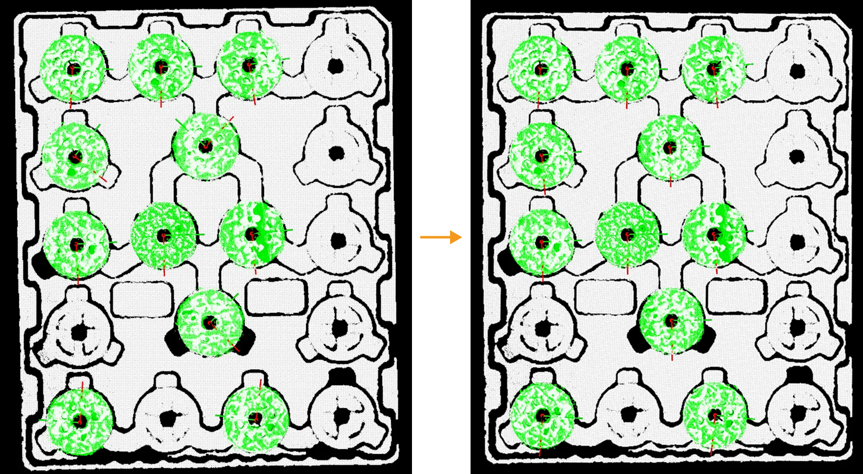
Adjust X-axis orientation: Fix the Z-axis of the pose obtained from coarse matching and rotate the X-axis to the specified direction. This parameter is typically used for circularly symmetric target objects (e.g., rings, brake discs) to ensure that the X-axis of the target object poses point in the same direction. |
|
Attempt to match using target object symmetry |
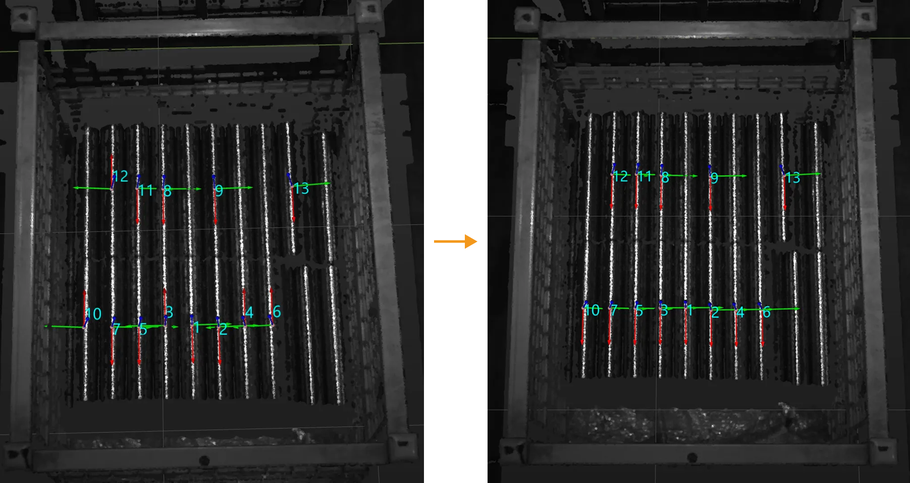
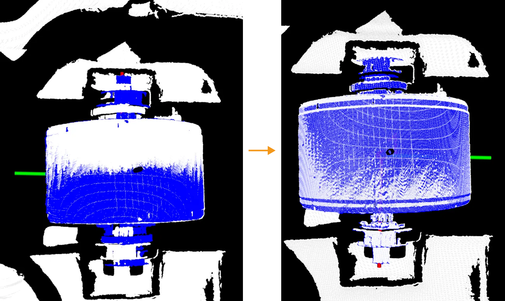
Uses unlikely poses calculated in the target object editor and manually configured symmetry to assist matching, helping to filter the coarsely matched poses. This parameter is typically used for the following two scenarios:
|
|
Confidence Settings
This parameter group is used to evaluate and filter matching results during 3D Matching to ensure matching accuracy and stability. For example, setting this parameter group properly can ensure that the target objects on the top layer that are normally placed can be accurately recognized.
First, this Step evaluates the matching results according to the set Result Validation Degree and calculates the confidence of the matching results. Then the confidence is compared with Confidence threshold to filter out qualified matches.
| Confidence of the matching result = the coincidence ratio between the point cloud model and the scene point cloud to be matched. |
| Parameter | Description |
|---|---|
Result Verification Degree |
Description: This parameter is used to set the degree of strictness applied when evaluating the matching results.
|
Search Radius |
Description: This parameter is used to determine the degree of overlap between the point cloud model and the scene point cloud. The smaller the search radius, the lower the matching result confidence; the larger the search radius, the higher the matching result confidence. You need to set this parameter when Result Verification Degree is set to Custom.
|
Sampling Interval |
Description: This parameter is used for the downsampling of the model and scene point cloud (only for evaluating the matching results). The larger the value, the fewer points in the sampled point cloud. You need to set this parameter when Result Verification Degree is set to Custom.
|
Confidence Threshold |
Description: If the confidence of the matching result is above the threshold, the matching result is valid. The higher the confidence value is, the more accurate the matching result is.
|
Consider Normal Deviation in Surface Matching |
Description: When verifying the surface matching results, consider the angle deviations between the normals of the points in the scene point cloud and their counterparts in the point cloud model. Once this parameter is enabled, the number of output matching results may be fewer, but the accuracy of the matching results will be enhanced.
|
Consider Holes in Surface Matching |
Description: During surface matching, if the outer contours of the point cloud model and the point cloud of the target object match, but either the point cloud of the target object or the point cloud model has holes, it can lead to mismatches (such as mismatches between rings and disks). Once this option is enabled, if the surface point cloud model and the target object cannot match in the holes, the corresponding surface matching confidence decreases. If the surface point cloud model has been edited and no longer accurately reflects the shape of the actual object, for example, if complex patterns in the center of the point cloud model have been deleted, it is recommended to disable this feature.
|
Confidence Strategy |
Description: This parameter is used to select the method to set the joint scoring strategy. Value list: Manual, Auto
Default value: Auto |
Joint Scoring Strategy |
Description: This parameter is used to select the scoring strategy used for verification. When Consider both surface and edge is selected, the parameters for surface matching and edge matching under Confidence Settings need to be set separately for better filtering of matching results.
|
Remove Coinciding Poses
| Parameter | Description | ||
|---|---|---|---|
Remove Poses of Coinciding Objects |
Description: This parameter is used to determine whether to enable the feature of removing coinciding objects. Default setting: Enabled
|
||
Coincidence Ratio Threshold |
Description: If the coincidence ratio of the masks, obtained by orthographically projecting the two object point clouds, exceeds this value, the pose with lower confidence will be removed. Set this parameter when Remove Poses of Coinciding Objects is enabled.
|
Remove Overlapped Poses
| Parameter | Description | ||
|---|---|---|---|
Remove Poses of Overlapped Objects |
Description: This parameter is used to determine whether to enable the feature of removing overlapped objects. Default setting: Enabled
|
||
Overlap Ratio Threshold |
Description: The threshold of the overlap ratio between the object and other objects. If the overlap ratio is above this value, the object will be considered overlapped. Set this parameter when Remove Poses of Overlapped Objects is enabled.
Default value: 30% |
||
Range of Scene Point Removal around Object |
Description: Within this range, points in the scene point cloud around the object will be removed, and the rest scene point cloud will be involved in the overlap detection. Set this parameter when Remove Poses of Overlapped Objects is enabled.
|
Output
| Parameter | Description | ||
|---|---|---|---|
Max outputs |
Description: This parameter specifies the maximum number of output target objects for successful matches. The larger the value, the longer the Step execution time. Default value: 10 Tuning recommendation: It is recommended to set this parameter appropriately and avoid setting it too high. The changes to this parameter will only take effect after re-running the Step, and the number of outputs will be limited based on the new matching result.
|
Visualization
| Parameter | Description |
|---|---|
Visualization Content |
Description: After “Debug Output” is enabled, the selected option will be generated and displayed in the Debug Output window.
|
Point Cloud Display Settings |
Description: This parameter is used to select the type of point cloud displayed in the visualization interface. When “Auto” is selected, the display type will be automatically set.
|
Display Poses |
Description: Once enabled, the pose will be displayed in the Debug Output window.
|