Configuration Workflow
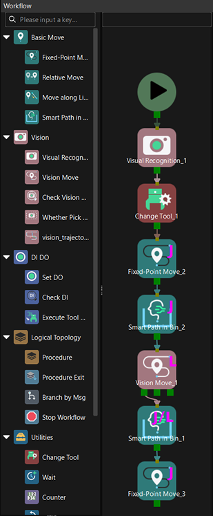
This section introduces the deployment prerequisites and the specific configuration workflow of the Picking Simulation tool, as shown in the figure below.

The following sections describe each step in detail.
Deployment Prerequisites
Before using the Picking Simulation tool, you need to first build a basic workflow in Mech-Viz to ensure the simulation process runs smoothly.
Before starting the simulation verification, make sure the current workflow meets the specifications supported by the picking simulation. If the workflow does not meet the requirements, the system will display an error message. The main items to check include:
-
Exit restrictions: The Set DO and Message Branch Steps only support fixed exits, and valid exits must be configured.
-
Prohibited Steps: The workflow must not contain the following unsupported Steps:
-
Classify
-
Update Scene Objects
-
Update Held Target Object
-
Update Pallet Pose
-
Check Tool
-
Counter
-
Check Completion
-
-
Structural restrictions: The workflow must not contain loop structures.
-
Length restrictions: The number of Steps in the workflow must not exceed 10,000.
-
Vision-type Step restrictions:
-
The workflow must contain one and only one Vision Move Step, and the Step does not support reusing vision results or sharing vision results.
-
The first Move-type Step in the workflow must be "Fixed-Point Move", and its target type must be set to "JPs". The JPs set in this Step are used as the robot’s initial JPs for each simulation.
-
| Before each picking simulation, make sure Keep Execution Status in the toolbar is disabled to avoid abnormal historical states of Steps such as Vision Move caused by multiple rounds of simulation, ensuring the accuracy of the simulation process. |
Layout Simulation
Before performing picking simulation, you need to first build a virtual scene that includes carriers and target objects. By properly setting the placement mode and number of target objects, the simulation environment should approximate the actual working conditions as closely as possible, providing a foundation for subsequent picking strategy verification.
Select Carrier
First, specify the carrier model to be used in the simulation scene. You can select an existing carrier from an existing solution, or create a new carrier and configure its parameters.
-
If an existing carrier meets the requirements, you can select it directly.
-
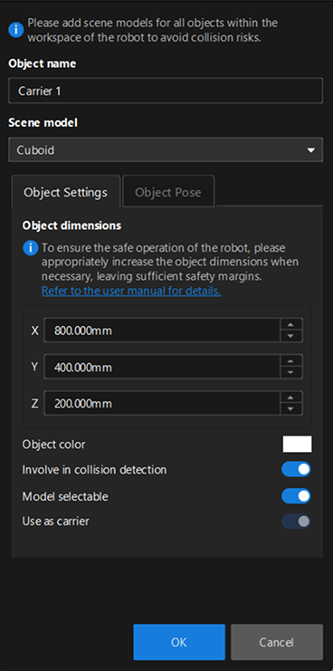
If you need a new carrier, click New carrier to enter the carrier configuration interface, where you can set the carrier name, scene model, carrier dimensions, and other parameters. The scene model is the carrier type setting, supporting bins, cuboids, and cylinders. When cuboid or cylinder is selected, the Use as carrier parameter is selected by default and cannot be deselected.
-
To modify an existing carrier configuration, click the Edit button.
For the specific configuration workflow of creating or editing a carrier, please refer to Scene Object Configuration.
| If you configure a carrier through , the Use as carrier option is not selected by default. Please select it manually. |
Configure Target Object
After the carrier is determined, you need to select the target objects for simulation and configure their display color. When selecting target objects:
-
If an existing target object in the solution meets the requirements, you can select it directly.
-
If you need a new target object, click New target object to go to the Target Object Editor to create a target object. You can create a target object template from an STL file or a basic geometric shape.
-
To modify an existing target object configuration, click the Edit button to enter the Target Object Editor.
After the target object template is configured, click the color swatch next to Target object color to set the display color of the target object in the simulation.
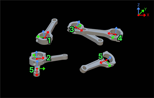
Configure Placement Mode
Based on actual production requirements, select the placement mode for target objects, including randomly stacked and neatly arranged.
Randomly Stacked
Target objects are randomly scattered in the carrier, simulating the randomly stacked situation in actual production. The following table describes the specific parameters and their configuration.
Parameter |
Description |
Placement pose |
This parameter is used to set the target object orientation. The target object coordinate system is aligned with the carrier coordinate system by default, meaning the X/Y/Z axes of the target object point in the same direction as the X/Y/Z axes of the carrier.
|
Drop zone |
This parameter is used to define the random drop range of target objects within the area. If a target object falls outside the area, it will be automatically removed and dropped again until the drop point is within the specified area.
|
Number of target objects |
This parameter is used to set the total number of target objects for the simulation. Please set a reasonable number of target objects based on actual requirements. The more target objects, the higher the simulation complexity, and the lower the running speed. |
Neatly Arranged
Target objects are placed in fixed positions and sequence, simulating neatly arranged situations. The following table describes the specific parameters and their configuration.
Parameter |
Description |
||
Placement pose |
This parameter is used to set the target object orientation. Please refer to the pose setting method under Randomly Stacked, and select the appropriate viewpoints and rotation angles to ensure the target object poses match the actual scenario. |
||
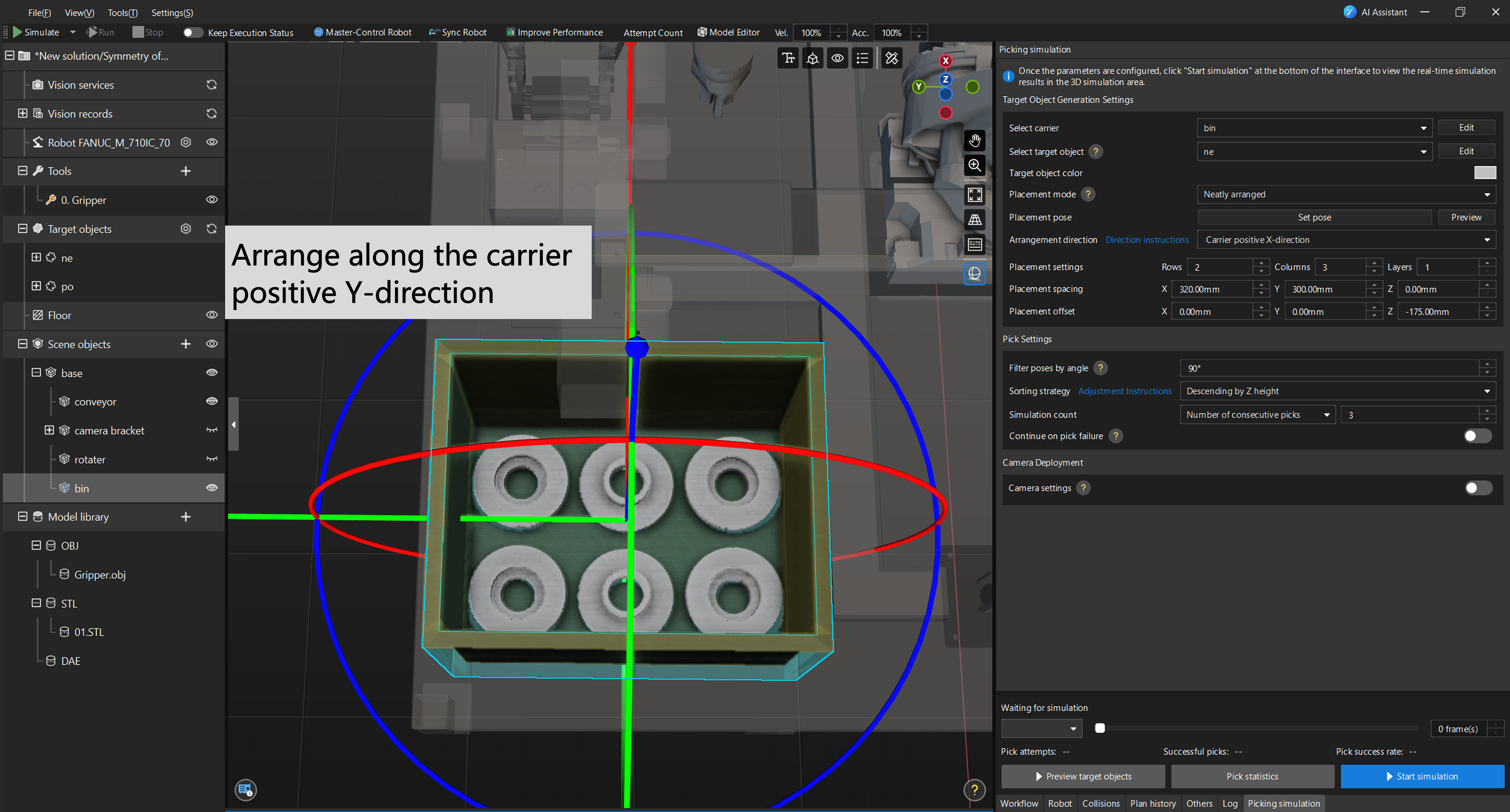
Arrangement direction |
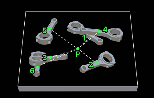
This parameter is used to specify the relative arrangement order of target objects in the carrier, including carrier positive X-direction, carrier negative X-direction, carrier positive Y-direction, and carrier negative Y-direction. The system will cyclically arrange the selected poses along the chosen direction. For example, when "Carrier positive X-direction" is selected, target objects with different poses will be arranged row by row along the carrier’s X-axis; when "Carrier positive Y-direction" is selected, target objects with different poses will be arranged column by column along the carrier’s Y-axis. The specific effects are shown in the figure below: 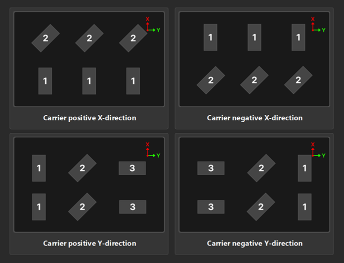
|
||
Placement settings |
This parameter is used to set the number of rows, columns, and layers of target objects to determine the overall arrangement structure. |
||
Placement spacing |
This parameter is used to set the spacing between adjacent target objects, which can be configured separately for the X, Y, and Z directions. If the spacing is too small, collisions may occur during picking. It is recommended to leave a safe distance. |
||
Placement offset |
This parameter is used to adjust the overall position of the target object arrangement in space. You can set offset values in the X, Y, and Z directions based on the carrier center to achieve overall translation of the target objects. |
When setting the above parameters, it is recommended to combine actual production and picking requirements and debug the target object placement through the visualization display in the 3D simulation space.
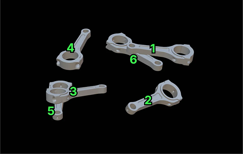
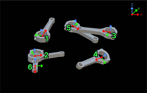
The example below demonstrates the placement settings, operations, and effects for target objects in neatly arranged mode, assuming two placement poses (positive and negative Z-axis directions):
-
When set to carrier positive X-direction:
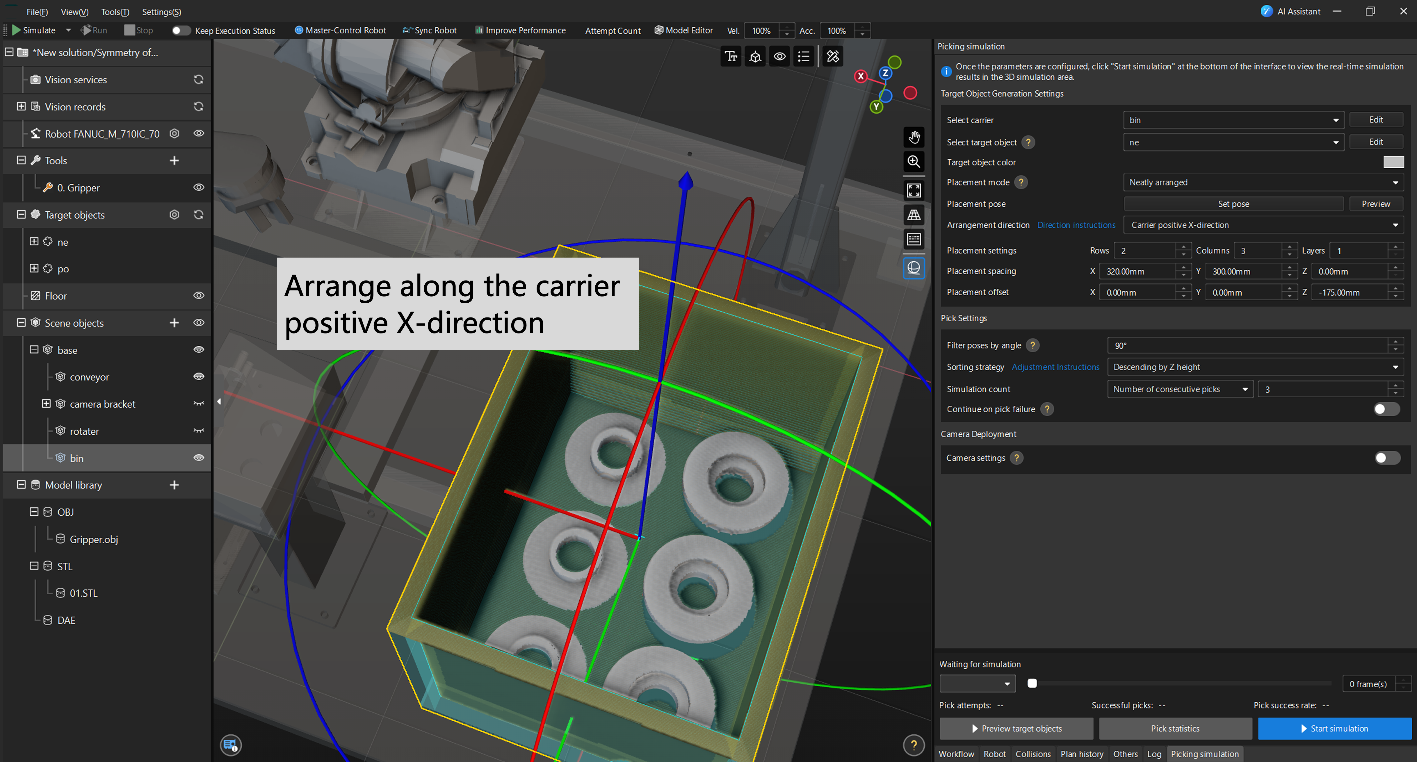
-
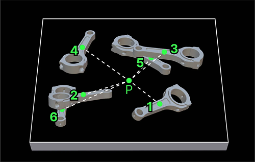
When set to carrier positive Y-direction:
-
Operation demonstration:
Pick Settings
After building the target object scene, you need to configure the picking strategy to more realistically reflect the actual picking logic and evaluate the impact of picking stability and failure on the overall picking effectiveness.
Filter Poses by Angle
By setting a pose filter angle threshold, you can filter out pick points with excessive tilt angles. When the angle between a pick point’s Z-axis and the world coordinate system’s Z-axis exceeds this threshold, the pick point will be filtered out and will not participate in subsequent path planning.
| If a large number of pick failures occur during the simulation, you can go to the Target Object Editor to adjust the pick point settings for the target object, so that more pick points can participate in planning. |
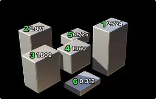
Set Sorting Strategy
The sorting strategy determines the priority order of picking. You can select different sorting strategies based on actual requirements. Multiple strategies are available, including descending by Z height, ascending by overlap ratio, ascending by Z-axis angle, etc. The details are as follows.
Sorting strategy |
Illustration |
Description |
Descending by Z height |
|
Sort target objects by the Z-coordinates of their pick points in descending order. |
Ascending by distance to carrier center |
|
Sort target objects by the distance from their pick points to the carrier center in ascending order. |
Ascending by overlap ratio |
|
Sort target objects by their overlap ratio with other objects in ascending order. |
Ascending by overlap ratio > Ascending by Z-axis angle |
|
Sort target objects first by overlap ratio with other objects in ascending order. When overlap ratios are the same or similar, further sort by Z-axis angle in ascending order. |
Ascending by overlap ratio > Ascending by distance to carrier center |
|
Sort target objects first by overlap ratio with other objects in ascending order. When overlap ratios are the same or similar, further sort by distance to carrier center in ascending order. |
Ascending by Z-axis angle |
|
Sort target objects by the angle between their pick point’s Z-axis and the world coordinate system’s Z-axis in ascending order. |
Set Simulation Count
Simulation count is used to control the number of times picking is repeatedly executed. Two modes are supported: Number of consecutive picks and Number of bins.
-
Number of consecutive picks: Picking is continuously executed within the same bin until the specified count is reached or there are no more target objects to pick in the bin. After each pick, the system records the result. This mode is suitable for verifying picking strategies in single-bin scenarios.
-
Number of bins: Picking is continuously executed across multiple bins. After each bin is completed, the next bin is automatically generated until the specified number of bins is reached. This mode is suitable for evaluating the stability of picking strategies in batch operations.
Continue on Pick Failure
This parameter specifies the handling method when picking fails.
-
When enabled, if pick planning for a target object fails, the system will remove the object with the highest Z-axis position and continue attempting to pick the remaining objects until the bin is empty. This mode is suitable for verifying the pick success rate of target objects under ideal conditions, ignoring the impact of interfering objects.
-
When disabled, if pick planning for a target object fails, all subsequent picking simulation will stop immediately. This mode is suitable for verifying the bin clearance rate in real scenarios, more closely approximating actual results.
| Continue on pick failure can be used in combination with Simulation count, and it affects the simulation picking process. |
-
When Continue on pick failure is enabled:
-
In Number of consecutive picks mode, only the specified number of picks is executed within a single bin, and the simulation ends when completed.
-
In Number of bins mode, after each bin is completed, the next bin is automatically generated, and picking continues until the specified number of bins is reached.
-
-
When Continue on pick failure is disabled, regardless of the simulation mode selected, the simulation is terminated immediately once pick planning fails.
Camera Deployment (Optional)
If you need to perform camera collision detection or verify the camera’s field of view coverage during picking simulation, or need to save image data captured by the camera during simulation for subsequent use in the vision recognition workflow, please enable camera deployment and perform the relevant configuration. This step is optional. If you do not have the above requirements, you can skip it without affecting the picking simulation process.
| Currently, only Eye to Hand camera installation is supported. |
Select Camera Type
First, enable Camera settings. Click Select camera, and in the drop-down list, you can select an existing camera or create a new one.
-
If an existing camera meets the requirements, you can select it directly.
-
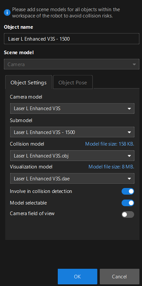
If you need a new camera, click New camera to enter the camera configuration window.
-
Enter a custom camera name in the Object name text box.
-
The scene model defaults to Camera and cannot be changed.
-
In the Object Settings interface, select the camera model, submodel (if applicable), collision model, and display model based on actual conditions.
-
It is recommended to enable Camera field of view during initial configuration to facilitate subsequent adjustment of the camera model pose.
-
The newly added camera model is positioned at the origin of the robot base coordinate system by default. Click Object Pose to switch the configuration interface, where you can modify various parameters to adjust the camera model’s pose.
-
-
To modify existing camera settings, click the Edit button.
| Under , right-click the camera name and select Show/hide camera field of view. This setting is linked with the Camera field of view toggle in the configuration window, meaning the visibility states of the two controls are always synchronized. |
Simulate Real Point Cloud
The system enables simulated point cloud noise by default to replicate the actual camera capture effect.
When enabled, you can set the point cloud filter angle to remove point clouds with angles greater than the set value, simulating the field-of-view limitation when a real camera acquires point clouds.
Simulation Verification
After all configurations are complete, you can proceed to the simulation verification phase. The system will simulate the robot picking process and collect real-time statistics on picking results and key data, facilitating comprehensive evaluation of the feasibility and risk points of the picking solution.
Start Simulation
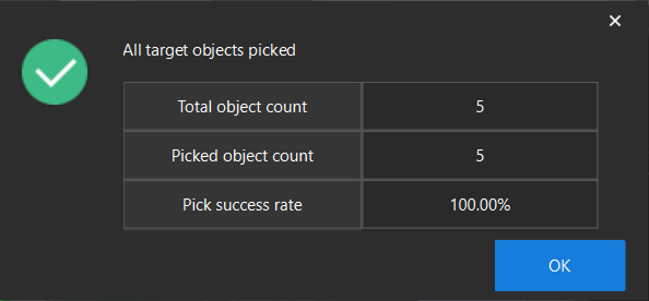
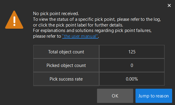
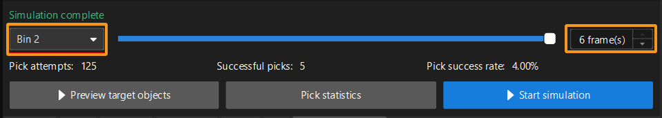
After completing the above configurations, you can proceed to the picking simulation verification phase. Click Start simulation, and the system will execute picking based on the current configuration and update Pick attempts and Successful picks in real time.
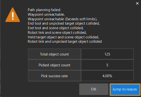
After the simulation is automatically completed, one of the following prompts will appear depending on whether all target objects were picked:
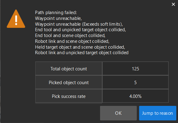
To view the picking dynamics, you can switch between bins, use the slider and frame controls to flexibly view the picking effects of different bins, and play the entire picking process frame by frame.
Pick Statistics
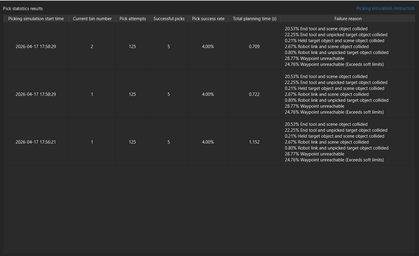
Pick statistics is used to view the detailed results and failure reasons of previous simulations, supporting quantitative analysis of picking performance.
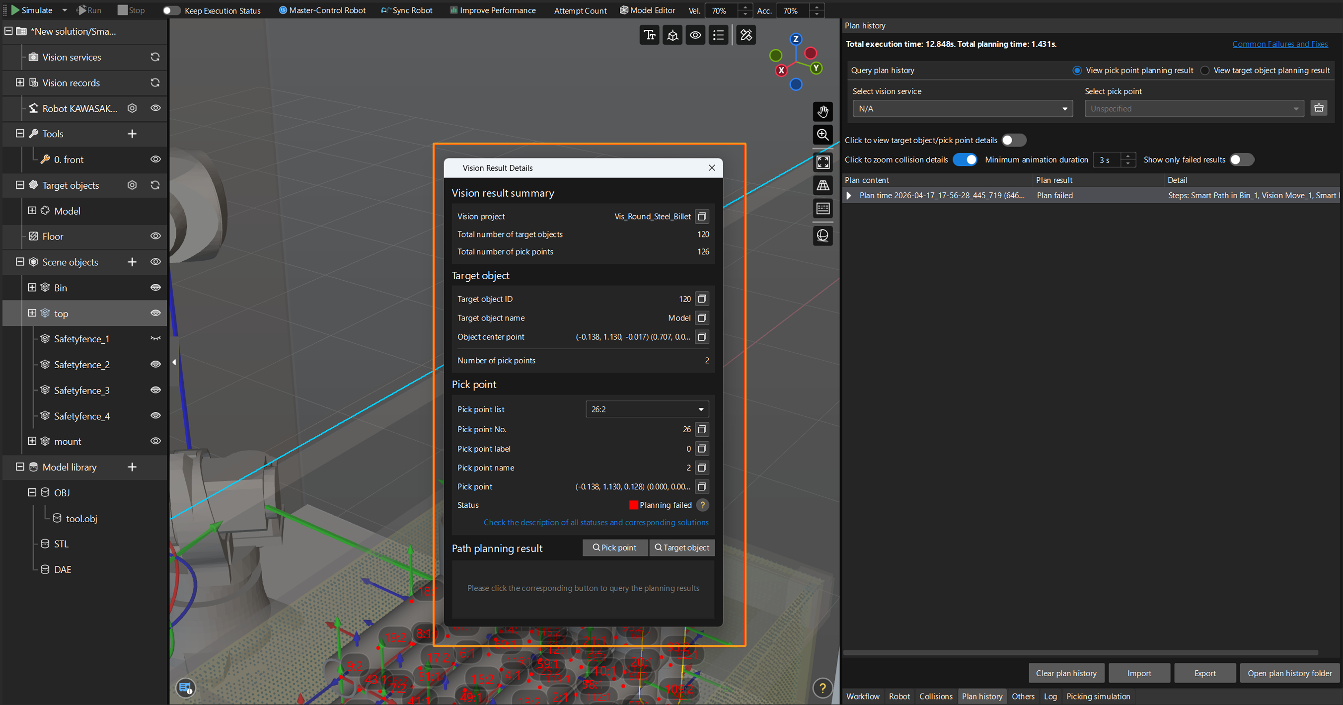
Click the Pick statistics button to open the statistics results window. The failure reasons can be used as a basis for optimizing picking strategies. It is recommended to pay close attention to frequently occurring failure types.
For further locating specific planning failure nodes or target objects, you can perform detailed analysis through the plan history function or by viewing logs.
| Only target objects with planning failures will be recorded in plan history. Target objects with successful planning will not be recorded. You can follow the failure prompt to navigate to Plan History to view the corresponding planning content and results. |
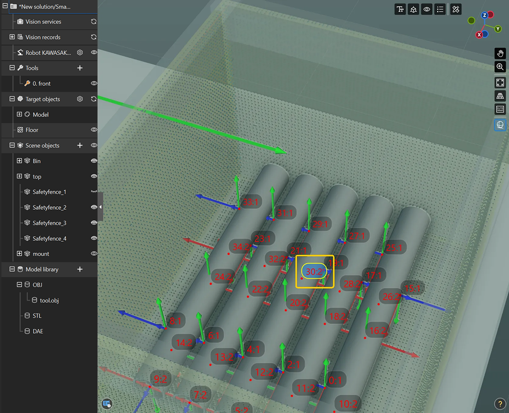
In addition, by double-clicking the pick point information on a target object, you can view the vision point details. In the Vision Result Details window, click Pick point and Target object under Path planning result to view the planning status and navigate to Plan History for troubleshooting.