Translate Poses along Given Direction
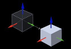
Input and Output
Parameter Description
Visualization Settings
| Parameter | Description |
|---|---|
Show Point Cloud In Selected Frame |
Default setting: Robot frame
|
Pose Type to Visualize |
Default setting: After.
|
Translation Direction Settings
| Parameter | Description |
|---|---|
Translation Distance |
Default value: 0
|
Translation Direction Source |
Default setting: CustomizedDirection (translate along the customized direction). Value list: CustomizedDirection, ObjectAxis
Instruction: Set the parameter according to actual situation. |
Examples
-
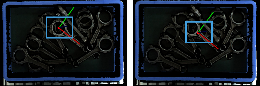
The figure below shows the pose before and after being translated 0.03 mm along the X axis of the object reference frame. In this example, ObjectAxis is selected as the Translation Direction Source; the specified axis is the X axis; and the Translation Distance is set to 0.03 mm.
-
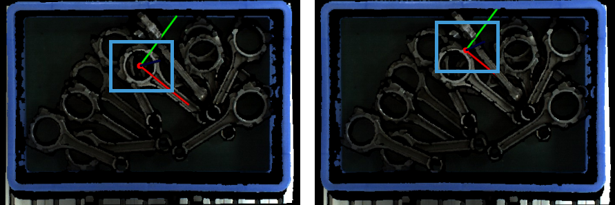
The figure below shows the pose before and after being translated 0.03 mm along the Y axis of the object reference frame. In this example, ObjectAxis is selected as the Translation Direction Source; the specified axis is the Y axis; and the Translation Distance is set to 0.03 mm.
-
The figure below shows the pose before and after being translated 0.08 mm along the Z axis of the object reference frame. In this example, ObjectAxis is selected as the Translation Direction Source; the specified axis is the Z axis; and the Translation Distance is set to 0.08 mm.
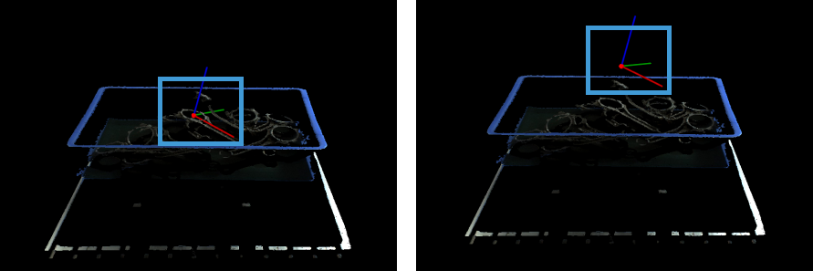
-
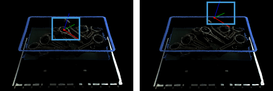
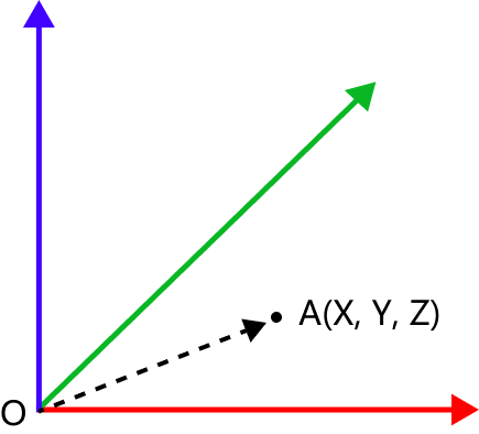
When CustomizedDirection is selected as the Translation Direction Source, you will need to set the values of X, Y, and Z in CustomizedDirection. As shown in the figure below, the path from the origin O to A (X, Y, Z) is the direction for the pose translation.
As shown below, in this example, the values of X, Y, and Z are all set to 5, and the Translation Distance is set to 0.08 mm. The figure shows the pose before (left) and after (right) being translated 0.08 mm along the customized direction.