Generate Path from Contour
Usage Scenario
This Step is typically used in edge gluing applications for objects such as rectangular hatches/glass.
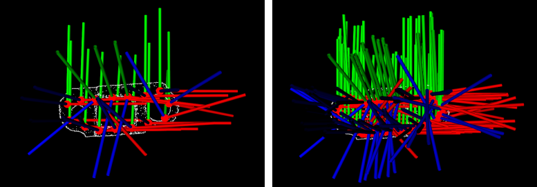
In the actual application process, due to factors such as the camera mounting angle and lighting, point clouds may lack necessary parts or have excessive noise. This can lead to changes or deviations in the starting point of the generated path, so it is recommended to use this Step only as an aid for path generation. Therefore, it is recommended to use this Step as an aid to generate a path.
For objects of the same type, you can obtain a stable path by following the steps below:
-
Use the object’s point cloud in conjunction with this Step to generate an initial path, and adjust the waypoints in the path.
-
Take the object’s point cloud as a point cloud model, use the adjusted waypoints as multiple pick points for the point cloud model, and set the object center point in the point cloud model.
-
Perform 3D matching on the object using the point cloud model and object center point, obtain the object’s pick points, and then use the “Map to Multiple Pick Points” Step to obtain multiple pick points for the object, which make up a stable path altogether.
Input and Output
Parameter Description
General Params
| Parameter | Description |
|---|---|
Mask Closing Kernel Size |
Parameter description: This parameter is used to set the size of the kernel when a closing operation is applied to the image mask. The unit is pixels.
|
Points Sample Size |
Parameter description: This parameter is used to specify the interval between waypoints in the generated path. The unit is pixels. The larger the value, the larger the interval between waypoints. Please refer to the tuning example for the corresponding result.
|
Edge Zoom Type |
Parameter description: This parameter is used to select the method to generate a path based on the edge point cloud. Value list: ByVertical, ByErode.
Default value: ByVertical |
Erode Kernel Size |
Parameter description: When the Edge Zoom Type is set to ByErode, this parameter is used to determine the distance between the path and the object edge and whether the path is within or outside the object edge. The unit is pixels. When the parameter value is positive, the generated path will be within the object edge. When the parameter value is negative, the generated path will be outside the object edge. Please refer to the tuning example for the corresponding result.
|
Vertical Move Real Dis |
Parameter description: When the Edge Zoom Type is set to ByVertical, this parameter is used to set the scaling distance along the vertical direction, measured in millimeters (mm). When the parameter value is positive, the generated path will be within the object edge. When the parameter value is negative, the generated path will be outside the object edge. Please refer to the tuning example for the corresponding result.
|
Smooth Points
| Parameter | Description |
|---|---|
Use Gaussian Filter |
Parameter description: This parameter is used to determine whether to use Gaussian filtering to smooth the edge points.
|
Gaussian Filter Radius |
Parameter description: This parameter is used to specify the radius of the Gaussian filter. The unit is pixels.
|
Gaussian Filter Sigma |
Parameter description: This parameter is used to set the sigma of the Gaussian filter.
|
Special Side Erode
This parameter group is designed for special applications, and it does not need to be adjusted in general.
| Parameter | Description |
|---|---|
Use Special Side Erode |
Parameter description: This parameter is used to control whether to enable special edge erosion treatment.
|
Interval Calc Tangent |
Parameter description: This parameter is used to set the interval for calculating tangent distance.
|
Special Side Erode Real Dis |
Parameter description: This parameter is used to set the actual erosion distance for special side erosion, measured in millimeters (mm).
|
Find Corners
| Parameter | Description |
|---|---|
Sample Size for Corner |
Parameter description: This parameter is used to set the coefficient of the downsampling on the edge point cloud. The unit is pixels. Downsampling is conducive to better detection of corners.
|
Quality Level |
Parameter description: This parameter is used to set the confidence threshold for corner detection, from 0.0 to 1.0. A larger value indicates a higher quality requirement for the detected corners.
|
Min Distance |
Parameter description: This parameter is used to set the minimum distance (px) between neighboring corners.
|
Max Corners |
Parameter description: This parameter is used to specify the maximum number of corners of the object.
|
Block Size |
Parameter description: This parameter is used to set the block size for corner detection, which is used to detect corners in regions where the edge of the target object point cloud is not obvious.
|
Use Harris Detector |
Parameter description: This parameter is used to determine whether to use Harris corner detector. Once this option is selected, you will need to set the K value.
|
K |
Parameter description: This parameter is used to set the response coefficient of the Harris detector, effective only when Use Harris Detector is selected.
|
Tuning Examples
Points Sample Size
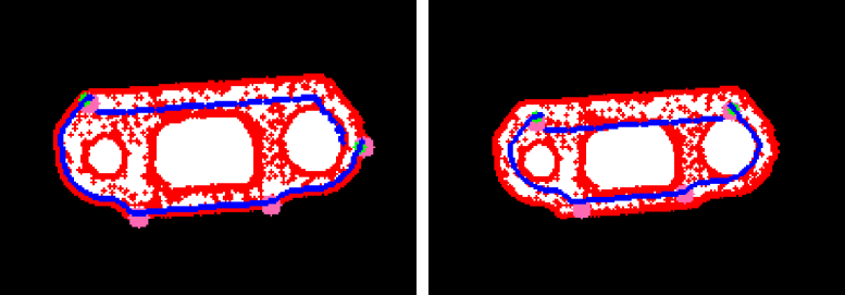
When Point Sample Size is set to 20 and 5 h, respectively, the waypoints in the generated path are shown below.
In the left figure, the Sampling Interval is 20, and the waypoints are sparse; in the right figure, the Sampling Interval is 5, and the waypoints are dense.
Erode Kernel Size
When Erode Kernel Size is set to 5 h and 15 h, respectively, the generated paths are shown below.
For the left figure, Erode Kernel Size is set to 5; for the right figure, Erode Kernel Size is set to 15. As the positive value increases, the generated path will shrink toward the inside of the object’s edge.
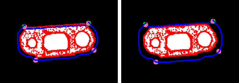
When Erode Kernel Size is set to −5 h and −20 h, respectively, the generated paths are shown below.
For the left figure, Erode Kernel Size is set to −5; for the right figure, Erode Kernel Size is set to −20. As the negative value decreases, the generated path will expand towards the outside of the object’s edge.
Vertical Move Real Dis
When Vertical Move Real Dis is set to 5 h and 15 h, respectively, the generated paths are shown below.
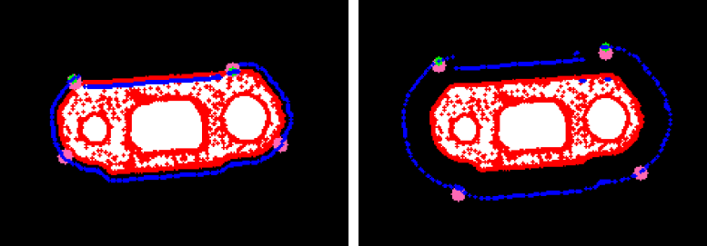
For the left figure, Vertical Move Real Dis is set to 5; for the right figure, Vertical Move Real Dis is set to 15. As the value of the positive number increases, the generated path will shrink towards the inside of the object edge.
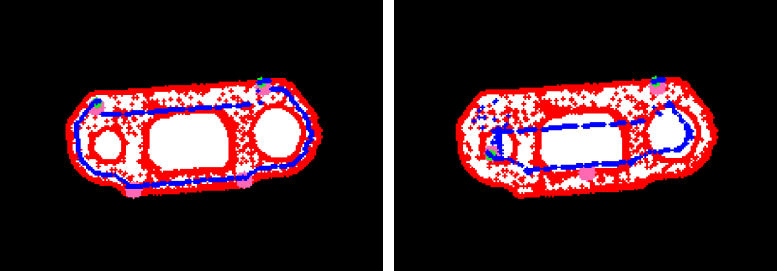
When Vertical Move Real Dis is set to −5 h and −20 h, respectively, the generated paths are shown below.
For the left figure, Vertical Move Real Dis is set to −5; for the right figure, Vertical Move Real Dis is set to −20. As the negative value decreases, the generated path will expand towards the outside of the object edge.