Frame Transformation
This topic introduces the "Frame Transformation" function in the "Advanced Pose Transformation" Step and its usage procedure.
Introduction
This function is used to transform input poses or point clouds from the current reference frame to a custom reference frame. By providing a reference pose for the custom reference frame, data alignment and switching between different reference frames can be achieved.
Usage Procedure
The following sections describe the specific usage of this function for pose and point cloud reference frame transformations respectively.
Transform the Reference Frame of Poses
Before performing a pose reference frame transformation, the Step ports must be configured first.
Configure Step Ports
-
Click the Config wizard1 button to open the pose transformation tool and select Frame transformation.
-
In the parameter panel on the right, select transformation type as Pose.
-
Click the OK button to complete the configuration.
The input and output ports after configuration are as follows:
Input
| Input port | Data type | Description |
|---|---|---|
Original Poses |
Pose [] |
Poses input to this port will be transformed to another reference frame. |
Customized Reference Frame |
Pose [] |
Poses will be transformed to the customized reference frame input to this port. |
Output
| Output port | Data type | Description |
|---|---|---|
Transformed Poses |
Pose [] |
Poses after the reference frame transformation. |
|
To apply the transformation, the poses and the customized reference pose must be defined in the same reference frame. |
Transform the Reference Frame of Poses
By inputting the Original Poses and Customized Reference Frame, you can transform the original poses to the custom reference frame. The following section describes how to use the "Advanced Pose Transformation" Step to perform pose reference frame transformations, with typical application scenarios in actual projects.
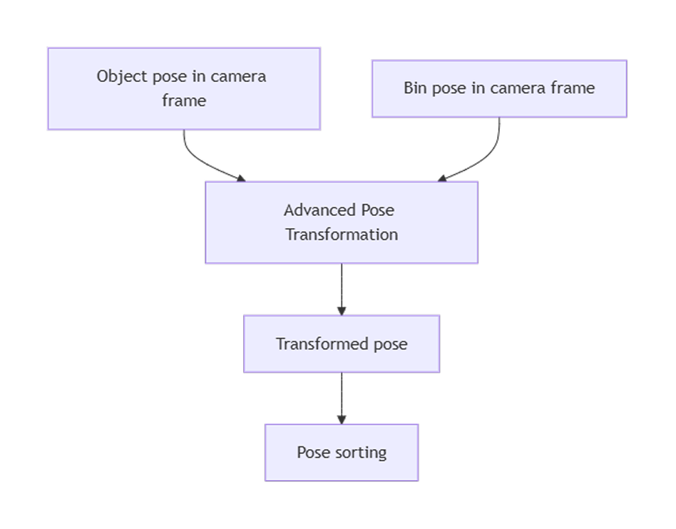
Scenario 1: Sort Target Objects by Bin Z-Axis When the Bin Is Tilted
In actual production, bins may be tilted overall, causing the Z values of target objects in the camera reference frame to not accurately reflect their actual height order inside the bin. In this case, the poses of the target objects need to be transformed to the bin’s own reference frame and sorted by the bin’s Z-axis to enable in-bin sorting or layered picking. The specific procedure is as follows:
-
Use the target object poses in the camera reference frame as "Original Poses" and the obtained bin pose as the "Customized Reference Frame". Use the "Advanced Pose Transformation" Step to transform the target object poses to the bin reference frame.
-
In the bin reference frame, use Steps such as pose sorting to sort the target objects by the Z-axis.
|
After sorting the target object poses, it is usually necessary to restore the sorted poses back to the original reference frame. This can be achieved using the Transform Poses Step. Input the sorted poses as "Original Poses" and the Customized Reference Frame from the "Advanced Pose Transformation" Step as "Reference Pose" to achieve the inverse transformation from the custom reference frame to the original reference frame. |
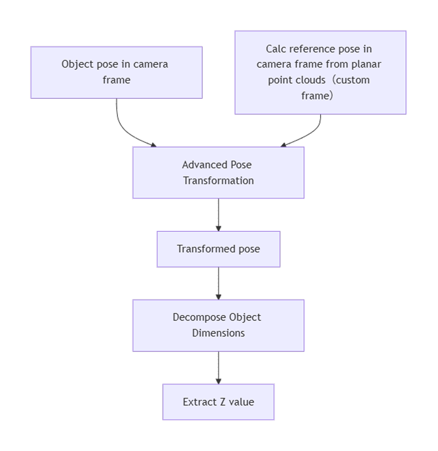
Scenario 2: Calculate Relative Height of Target Objects When the Reference Plane Is Tilted
In some scenarios, target objects are placed on a non-horizontal reference plane (such as a tilted conveyor belt or fixture). In this case, directly reading the Z values of target objects in the camera reference frame cannot accurately reflect the true height of the target objects relative to the reference plane.
To obtain the relative height of target objects, the poses of the target objects need to be transformed to a custom reference frame with the reference plane as the XY plane, so that the Z-axis is perpendicular to the reference plane, enabling accurate calculation of the relative height of target objects. The specific procedure is as follows:
-
Use Steps such as Calc Poses and Dimensions from Planar Point Clouds to calculate a reference pose (i.e., the custom reference frame) based on the reference plane point cloud in the camera reference frame.
-
Use the "Advanced Pose Transformation" Step to transform the original target object poses to this custom reference frame.
-
Decompose the transformed poses and extract the Z component from the translation vector as the height of the target objects relative to the reference plane.
The Z value after transformation represents the actual height of the target object relative to the reference plane. If the pose needs to be used in the original reference frame subsequently, it can be restored using the "Transform Poses" Step. |
Transform the Reference Frame of Point Clouds
Before performing a point cloud reference frame transformation, the Step ports must be configured first.
Configure Step Ports
-
Click the Config wizard1 button to open the pose transformation tool and select Frame transformation.
-
In the parameter panel on the right, select transformation type as Point cloud.
-
Click the OK button to complete the configuration.
The input and output ports after configuration are as follows:
Input
| Input port | Data type | Description |
|---|---|---|
Original Point Clouds |
PointCloud [] |
Point clouds input to this port will be transformed to another reference frame. |
Customized Reference Frame |
Pose [] |
Point clouds will be transformed to the customized reference frame input to this port. |
Output
| Output port | Data type | Description |
|---|---|---|
Transformed Point Clouds |
PointCloud [] |
Point clouds after the reference frame transformation. |
|
To apply the transformation, the point clouds and the customized reference pose must be defined in the same reference frame. |
Transform the Reference Frame of Point Clouds
By inputting the Original Point Clouds and the Customized Reference Frame, you can transform the original point clouds to the custom reference frame. The following section describes how to use the "Advanced Pose Transformation" Step to perform point cloud reference frame transformations, with typical application scenarios in actual projects.
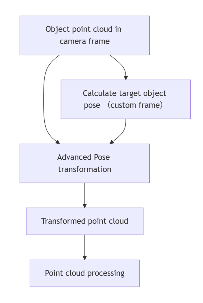
Scenario 1: Camera Capture Direction Does Not Align with the Target Object Plane
In actual applications, due to factors such as target object reflections, 3D cameras often cannot be positioned perpendicular to the target object surface and are instead mounted at a certain tilt angle. This causes the captured point cloud to be tilted in the camera reference frame. If point cloud processing such as point filtering is performed directly in this reference frame, valid points may be mistakenly removed or noise points may be retained, affecting subsequent plane fitting, feature extraction, and measurement accuracy.
To improve processing results, a custom reference frame can be constructed based on the main plane point cloud of the target object (with the Z-axis perpendicular to the target object plane). The specific procedure is as follows:
-
Use Steps such as Calc Poses and Dimensions from Planar Point Clouds to calculate a reference pose (i.e., the custom reference frame) based on the target object plane point cloud in the camera reference frame.
-
Use the "Advanced Pose Transformation" Step to transform the original target object point cloud to this custom reference frame for point cloud processing.
|
After point cloud preprocessing, it is usually necessary to restore the processed point cloud to the original reference frame. In the Transform Point Clouds Step, select the "UseCorrespondenceInput" transformation type, input the processed point cloud as "Original Point Cloud", and the Customized Reference Frame from the "Advanced Pose Transformation" Step as the "Reference Pose" to achieve the inverse transformation from the target object reference frame to the camera reference frame. |
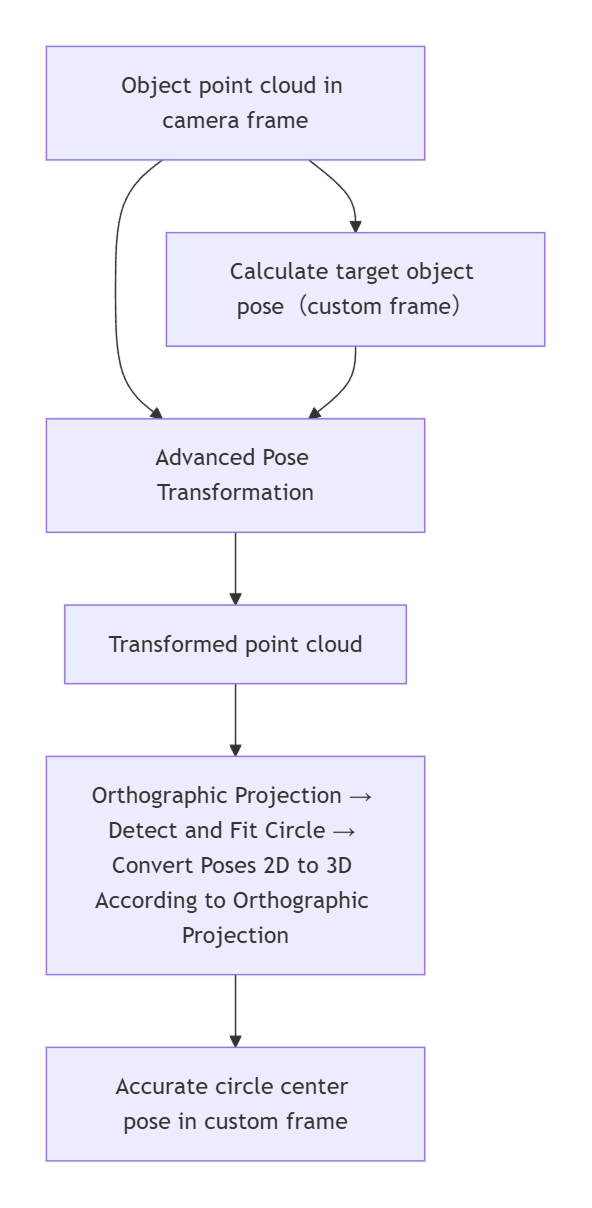
Scenario 2: Obtain Precise Circle Center (Based on Orthographic Projection)
In some high-precision applications, it is difficult to accurately obtain the positions of geometric features such as circle centers through 3D matching alone. To improve detection accuracy, a method combining point cloud reference frame transformation and orthographic projection can be used. The point cloud is transformed to the target object’s reference frame for 2D feature extraction, and then the result is restored to the camera reference frame to obtain a higher-precision circle center pose. The specific procedure is as follows:
-
Use Steps such as Calc Poses and Dimensions from Planar Point Clouds to calculate a reference pose (i.e., the custom reference frame) based on the target object plane point cloud in the camera reference frame.
-
Use the "Advanced Pose Transformation" Step to transform the original target object point cloud to this custom reference frame.
-
For the transformed point cloud, use Steps such as Orthographic Projection for 2D feature extraction to calculate the circle center pose.
|
After obtaining a precise circle center pose, it is usually necessary to restore it to the camera reference frame. This can be achieved using the Transform Poses Step: input the calculated circle center pose as "Original Pose" and the Customized Reference Frame from the "Advanced Pose Transformation" Step as "Reference Pose" to achieve the inverse transformation from the target object reference frame to the camera reference frame. |