Inference Configuration Tool
This section introduces the Inference Configuration tool for post-processing in deep learning Steps, and explains how to use it.
Introduction
The Inference Configuration tool is a dedicated tool for configuring and optimizing post-process parameters in Steps such as "Deep Learning Model Package Inference". With this tool, you can flexibly adjust inference parameters for different types of model packages (such as Image Classification, Defect Segmentation, Object Detection, etc.), configure validation rules for multi-model packages, and thereby improve the accuracy and applicability of inference results. The Inference Configuration tool supports parameter group management and visual parameter tuning.
Start the Feature
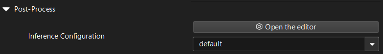
In the Step parameters panel of the "Deep Learning Model Package Inference" Step or the "Pick Anything V2" Step, click the Open the editor button of the Inference Configuration parameter to open the Inference Configuration tool.
Interface Description
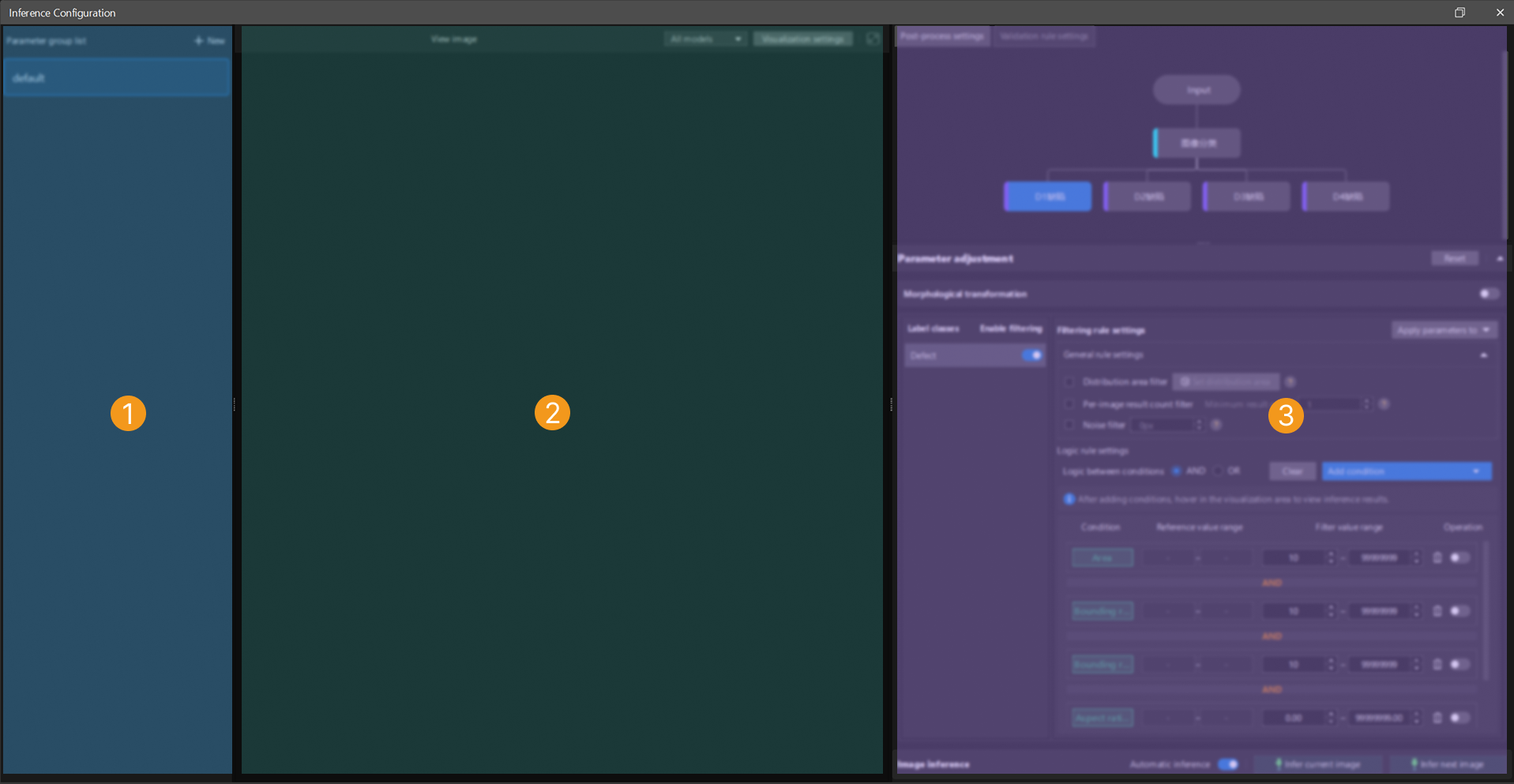
The interface of the Inference Configuration tool is shown below.
The functional areas in the above interface are described in the following table.
| No. | Area | Description |
|---|---|---|
1 |
Parameter group list |
Displays all created parameter groups. You can create, delete, duplicate, and switch parameter groups to manage inference configurations for different scenarios. |
2 |
Image visualization area |
Displays the model inference results. You can configure label font colors and mask colors for different label classes in "Visualization Settings". If a multi-model package is used for inference, you can also switch the visualization scope by selecting All models or Selected model at the top of the visualization area. |
3 |
Inference configuration area |
Used to configure the processing logic for inference results, including post-process settings and validation rule settings.
|
Inference Configuration Procedure
You can follow the procedure below to configure inference:
-
After opening the tool, create a new parameter group or select an existing parameter group for editing.
-
In the Post-process settings tab of the inference configuration area on the right, adjust the key parameters according to the current model type. While adjusting parameters, you can observe the changes in the visualization area on the left to verify the parameter adjustment results in real time.
-
If a multi-model package is being used, switch to the Validation rule settings tab to define the logical relationships between the results of multiple models.
-
At the top of the visualization area, click Visualization Settings to set mask colors for different label classes or adjust label font colors to improve the distinction between results.
-
After the configuration is complete, click Save. The system will automatically apply the current parameter group configuration to the inference Steps that use this parameter group.
Post-Process Settings
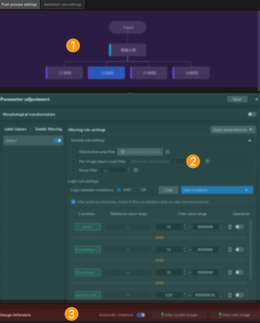
The post-process settings page is shown below.
The functional areas in the above interface are described in the following table.
| No. | Area | Description |
|---|---|---|
1 |
Model navigation |
Displays the models included in the imported model package. If a multi-model package is used, you can click different models to switch to the corresponding post-process parameters for adjustment. |
2 |
Parameter adjustment |
Used to configure the post-process parameters of the currently selected model. After adjustment, you can click Infer current image in the visualization area to view the adjustment results in real time. Click Reset to restore the default parameter configuration. |
3 |
Image inference |
Infer images based on the set parameters and view the inference results in the visualization area. The "Automatic inference" function is enabled by default. Click Infer current image to process a single image with the current parameters. Click Infer next image to automatically load and process the next image in the sequence. |
The following sections describe the post-process parameters for different model package inference tasks. You can select the corresponding section based on the type of model package you use.
Image Classification
The adjustable post-process parameters for an Image Classification model package are as follows.
| Parameter | Description | ||
|---|---|---|---|
Confidence threshold |
This parameter is used to set the confidence threshold for image classification. Results with confidence above this threshold will be retained.
|
||
Generate class activation maps |
This parameter is used to view which pixel regions in the image contribute more to the image classification result. Blue represents lower contribution and red represents higher contribution. Enabling Generate class activation maps will slow down the model package inference speed. It is recommended to use this function only for debugging and analysis, not in production environments.
|
Defect Segmentation
The adjustable post-process parameters for a Defect Segmentation model package are as follows.
Morphological transformation
| Parameter | Description |
|---|---|
Morphological transformation |
Enabling this parameter will apply morphological processing to the defect segmentation masks.
|
Morphological transformation type |
This parameter is used to select the morphological post-processing method for masks. Options: Dilation, Erosion, Opening, Closing
Adjustment: Set this parameter based on actual requirements. |
| Parameter | Description | ||
|---|---|---|---|
Label classes |
Displays the list of defect classes labeled during training in Mech-DLK.
|
||
Enable filtering |
This parameter specifies whether to enable filtering rules for the corresponding label class.
|
Filtering rule settings
| Parameter | Description |
|---|---|
Apply parameters to |
Used to select whether to apply the configured filtering rule parameters to a specified class or all classes. |
Distribution area filter |
A general filtering rule. After setting the distribution area, only inference results within the distribution area will be retained. Configure this through the "Set distribution area" button.
|
Per-image result count filter |
A general filtering rule. Used to set the minimum number of inference results in a single image. Only when the number of results is greater than or equal to this value will the inference results of the image be retained.
|
Noise filter |
A general filtering rule. Used to set the minimum area of a single inference result. Results with an area smaller than the set value will be filtered out.
|
Logic between conditions |
A logic filtering rule. Used to uniformly set the logic between conditions (AND/OR) for multiple added filtering conditions (such as area, aspect ratio of bounding rectangle, circularity, etc.). Different condition items are combined according to the "Logic between conditions" setting (AND/OR); when the same condition item is added multiple times, it is always combined with OR logic, regardless of the "Logic between conditions" setting.
|
|
Instance Segmentation
The adjustable post-process parameters for an Instance Segmentation model package are as follows.
| Parameter | Description |
|---|---|
Morphological transformation |
Enabling this parameter will apply morphological processing to the instance segmentation masks.
|
Morphological transformation type |
This parameter is used to select the morphological post-processing method for masks. Options: Dilation, Erosion, Opening, Closing
Adjustment: Set this parameter based on actual requirements. |
Confidence threshold |
This parameter is used to set the confidence threshold for instance segmentation. Results with confidence above this threshold will be retained. Adjustment: Set this parameter based on actual requirements. |
Object Detection
The adjustable post-process parameters for an Object Detection model package are as follows.
| Parameter | Description |
|---|---|
Confidence threshold |
This parameter is used to set the confidence threshold for object detection. Results with confidence above this threshold will be retained. Adjustment: Set this parameter based on actual requirements. |
Text Detection
The adjustable post-process parameters for a Text Detection model package are as follows.
| Parameter | Description |
|---|---|
Text sorting order |
This parameter specifies the sorting order of text detection results, which affects the order of subsequent text recognition or display.
|
Filtering rule settings
| Parameter | Description |
|---|---|
Filtering rule settings |
Used to further filter text detection results, including general rules and logic rules. By properly configuring filtering rules, you can improve the accuracy of text detection and reduce false detections and missed detections. |
Confidence threshold |
A general filtering rule. Used to set the confidence threshold for text detection. Results with confidence above this threshold will be retained.
|
Logic between conditions |
A logic filtering rule. Used to uniformly set the logic between conditions (AND/OR) for multiple added filtering conditions (such as area, aspect ratio of bounding rectangle, circularity, etc.). Different condition items are combined according to the "Logic between conditions" setting (AND/OR); when the same condition item is added multiple times, it is always combined with OR logic, regardless of the "Logic between conditions" setting.
|
|
Text Recognition
The adjustable post-process parameters for a Text Recognition model package are as follows.
| Parameter | Description | ||
|---|---|---|---|
Text connection |
Enabling this parameter allows the recognized text to be concatenated.
|
||
Text concatenation |
This parameter is used to select the method for concatenating text.
|
||
Text modification |
This parameter is used to perform custom modifications on the text in recognition results. Multiple modification methods are supported to meet different text processing needs. Options: Character replace, Fixed-position replace
Click + to select a text modification method.
|
Unsupervised Segmentation
The adjustable post-process parameters for an Unsupervised Segmentation model package are as follows.
| Parameter | Description |
|---|---|
Confidence threshold |
This parameter is used to set the confidence threshold for unsupervised segmentation. Drag the slider to adjust the threshold. The red portion represents the NG (not good) range, and the green portion represents the OK (good) range. If the segmentation confidence is lower than the OK threshold, the result is OK. If it is higher than the NG threshold, the result is NG.
|
Multi-Model Package
A multi-model package is a combination of multiple single model packages connected in series, parallel, or a combination of both. You can click a model in the model navigation area to select the model whose parameters you want to adjust, and then configure the corresponding settings in the parameter adjustment area. The parameter settings for each model are the same as those of the corresponding single model package. For details, see the parameter descriptions of the respective single model packages above.
Pick Anything V2
The adjustable post-process parameters for a Pick Anything V2 model package are as follows.
Morphological transformation
| Parameter | Description |
|---|---|
Morphological transformation |
Enabling this parameter will apply morphological processing to the surface segmentation masks.
|
Morphological transformation type |
This parameter is used to select the morphological post-processing method for masks. Options: Erosion by ratio, Erosion by pixels
Adjustment: Set this parameter based on actual requirements. |
| Parameter | Description |
|---|---|
Label classes |
Displays the surface classes labeled during training in Mech-DLK, which are graspable surfaces and occluded surfaces.
|
Enable filtering |
This parameter specifies whether to enable filtering rules for the corresponding label class.
|
Filtering rule settings
| Parameter | Description |
|---|---|
Apply parameters to |
Used to select whether to apply the configured filtering rule parameters to a specified class or all classes. |
Distribution area filter |
A general filtering rule. After setting the distribution area, only inference results within the distribution area will be retained. Configure this through the "Set distribution area" button.
|
Logic between conditions |
A logic filtering rule. Used to uniformly set the logic between conditions (AND/OR) for multiple added filtering conditions (such as area, aspect ratio of bounding rectangle, circularity, etc.). Different condition items are combined according to the "Logic between conditions" setting (AND/OR); when the same condition item is added multiple times, it is always combined with OR logic, regardless of the "Logic between conditions" setting.
|
|
Validation Rule Settings (Multi-Model Package)
In scenarios where multiple models work together, the results of a single model may not be sufficient to make a final judgment. "Validation rule settings" allows you to define the logical relationships between the results of multiple models to generate the final judgment result (OK or NG).
|
Validation rules only need to be configured in scenarios where a multi-model package is used for deep learning inference. If a single model package is used for inference, this configuration interface will not be shown. |
Validation Rule Description
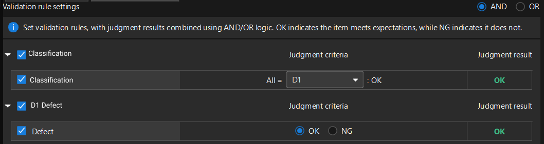
In the Validation rule settings area, set the validation rules. The judgment results can be combined using AND/OR logic. OK indicates that the item meets the expectation, and NG indicates that it does not.
-
AND: The final judgment result is OK only when all selected rules meet their respective judgment criteria.
-
OR: The final judgment result is OK as long as one of the selected rules meets its own judgment criterion.
Judgment criterion: Set whether a certain situation is expected or not expected when it occurs.
Judgment result: Displays the actual result based on the configured judgment criterion.
Validation process: The system first independently evaluates each selected validation rule to obtain the corresponding judgment result. Then, based on the configured logic (AND/OR), the results of each rule are combined to output the final judgment result for the current image.
Validation Rule Configuration Procedure
-
Click the Validation rule settings tab in the inference configuration area.
-
Select the logical relationship between the models (AND or OR).
-
Select the rules from the list that should participate in the judgment, and define the judgment criterion for each rule.
-
Verify that the final judgment result meets the expectation based on the configured judgment criteria. After confirmation, click Save to save the validation rules to the parameter group.
To help you understand, the following two scenario examples demonstrate the above procedure.
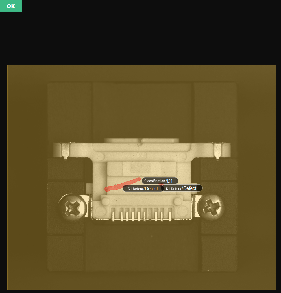
Scenario Example 1
As shown in the figure, the following example shows how to set validation rules, with the expectation of detecting both the D1 connector housing and D1 connector housing scratches in the image.
-
Set the validation rules and select "AND" logic for combining judgment results.
-
Set the judgment criterion for each model and verify the judgment result.
-
Set the judgment criterion of the Image Classification model to "All = D1, then OK", meaning that when all classification results of the current image are D1 connector housing, the expectation is met, and the judgment result is OK.
-
Set the judgment criterion of the Defect Segmentation model to "OK", meaning that when connector housing scratches are detected in the current image, the expectation is met, and the judgment result is OK.
-
-
When the judgment results of both models are OK, the final judgment result displayed in the upper-left corner of the visualization area should be OK.
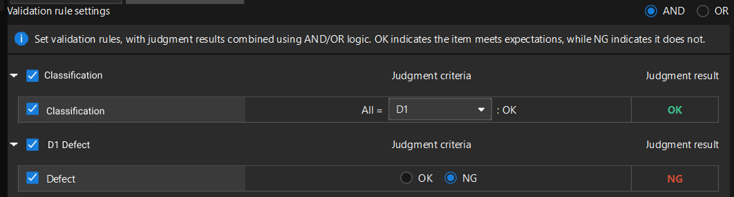
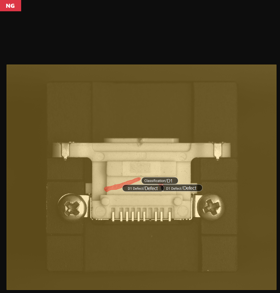
Scenario Example 2
As shown in the figure, the following example shows how to set validation rules, with the expectation of detecting the D1 connector housing in the image but not expecting D1 connector housing scratches.
-
Set the validation rules and select "AND" logic for combining judgment results.
-
Set the judgment criterion for each model and verify the judgment result.
-
Set the judgment criterion of the Image Classification model to "All = D1, then OK", meaning that when all classification results of the current image are D1 connector housing, the expectation is met, and the judgment result is OK.
-
Set the judgment criterion of the Defect Segmentation model to "NG", meaning that when connector housing scratches are detected in the current image, the expectation is not met, and the judgment result is NG.
-
-
When the judgment result of the Image Classification model is OK and the judgment result of the Defect Segmentation model is NG, the final judgment result displayed in the upper-left corner of the visualization area should be NG.
Reference Information
Filtering Condition Descriptions
| Condition | Description |
|---|---|
Basic options |
|
Area |
The total number of pixels in a single recognized target region. Used to filter targets that are too large or too small. |
Total area |
The sum of the pixel counts of all recognized targets in the current detection region. Used to control the total coverage of targets and avoid excessive or large-area target clusters. |
Bounding rectangle height |
The height (in pixels) of the axis-aligned bounding rectangle of the target, i.e., the height of the smallest rectangle parallel to the coordinate axes. Used to filter the maximum or minimum vertical span of a target. Suitable for non-tilted or aligned targets; the value may be larger than the actual height for tilted targets. |
Bounding rectangle width |
The width (in pixels) of the axis-aligned bounding rectangle of the target, i.e., the width of the smallest rectangle parallel to the coordinate axes. Used to filter the maximum or minimum horizontal span of a target. Suitable for non-tilted or aligned targets; the value may be larger than the actual width for tilted targets. |
Aspect ratio of bounding rectangle |
The ratio of the longer side to the shorter side of the axis-aligned bounding rectangle of the target. Used to distinguish targets of different shapes, such as distinguishing elongated scratches from round pits. |
Principal axis angle |
The angle (in degrees) between the principal axis of the target and the horizontal direction. Used to filter targets with a specific orientation. |
Advanced options |
|
Circularity |
Measures how close the shape of the target is to a perfect circle. A value closer to 1 indicates a rounder shape. Used to distinguish circular targets (such as screw holes) from irregularly shaped targets (such as cracks and stains). |
Bounding rectangle center X |
The X coordinate of the center of the axis-aligned bounding rectangle. Used to filter the horizontal position of a target in the image. |
Bounding rectangle center Y |
The Y coordinate of the center of the axis-aligned bounding rectangle. Used to filter the vertical position of a target in the image. |
Inradius |
The radius of the largest circle that can be completely contained within the target. Used to evaluate the "solidity" of the target or the minimum through-hole size, and to exclude targets with hollows or that are not compact. |
Circumradius |
The radius of the smallest circle that can completely enclose the target. Used to filter the maximum enclosing size of a target. Commonly used for rough positioning of circular workpieces or upper limit size filtering. |
Inscribed rectangle width |
The width of the largest rectangle that can be completely contained within the target. Used to filter the horizontal dimension of the effective area inside the target and to exclude objects with severe edge damage. |
Inscribed rectangle height |
The height of the largest rectangle that can be completely contained within the target. Used to filter the vertical dimension of the effective area inside the target and to exclude objects with severe edge damage. |
Centroid X |
The horizontal position of the grayscale or geometric centroid of the target region in the image coordinate system. Compared to the geometric center, it better reflects the position of the actual core. Used to filter targets that appear in a specific horizontal region of the image. |
Centroid Y |
The vertical position of the grayscale or geometric centroid of the target region in the image coordinate system. Compared to the geometric center, it better reflects the position of the actual core. Used to filter targets that appear in a specific vertical region of the image. |
Bounding rectangle top-left X |
The X coordinate of the top-left corner of the axis-aligned bounding rectangle of the target. Used to filter the starting horizontal position of a target in the image. |
Bounding rectangle top-left Y |
The Y coordinate of the top-left corner of the axis-aligned bounding rectangle of the target. Used to filter the starting vertical position of a target in the image. |
Bounding rectangle bottom-right X |
The X coordinate of the bottom-right corner of the axis-aligned bounding rectangle of the target. Used to filter the ending horizontal position of a target in the image. |
Bounding rectangle bottom-right Y |
The Y coordinate of the bottom-right corner of the axis-aligned bounding rectangle of the target. Used to filter the ending vertical position of a target in the image. |
Rotated bounding rectangle width |
The width (in pixels) of the minimum-area bounding rectangle of the target, which can be rotated to any angle. It fits the actual shape of the target more closely. Suitable for filtering the width of tilted targets. |
Rotated bounding rectangle height |
The height (in pixels) of the minimum-area bounding rectangle of the target, which can be rotated to any angle. It fits the actual shape of the target more closely. Suitable for filtering the height of tilted targets. |
|
An axis-aligned bounding rectangle is the smallest enclosing rectangle whose four sides are strictly parallel to the image coordinate axes (horizontal/vertical directions). |