Dual Robot Relative Pose Calibration
This topic introduces the "Dual Robot Relative Pose Calibration" function in the "Advanced Pose Transformation" Step and its usage procedure.
Introduction
This function is used to calibrate the spatial pose relationship between two robots, i.e., to calculate the pose of one robot in the reference frame of another robot. The following two hardware configurations are supported:
-
Camera on one robot: One robot carries a camera, while the other carries a calibration board. The camera calibrates the board to determine the relative pose between the two robots.
-
Cameras on both robots: Both robots are equipped with cameras and capture the same fixed calibration board. The relative pose between the two robots is calculated using the camera extrinsic parameters.
After calibration, the relative pose between the two robots is output through the output port, which can be used for subsequent reference frame transformations and data merging operations to facilitate dual-robot collaboration. Additionally, previously saved pose relationships can be directly loaded and reused without repeating the calibration.
Usage Procedure
This section introduces three methods for obtaining the relative pose relationship between two robots. Users can select the appropriate procedure based on actual requirements:
Calibrate Relative Pose with Camera Mounted on a Single Robot
This method is suitable for scenarios where the relative pose relationship between two robots has not yet been established, and only one robot has a camera mounted for calibration.
Select Creation Type
-
Click the Config wizard1 button to open the pose transformation tool and select Dual robot relative pose calibration.
-
In the parameter area on the right, select the creation type as Create new relationship, and set the camera setup to Camera on one robot.
Click the OK button to enter the dual robot relative pose calibration process.
Calibrate Dual Robot Pose Relationship
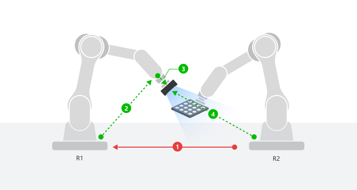
The overall process for dual robot relative pose calibration is shown in the figure below.

By default, Robot R2’s coordinate system is used as the reference frame. A camera is mounted on Robot R1, and the pose of Robot R1 in Robot R2’s coordinate system is calculated. The steps are as follows:
-
Acquire EIH extrinsic parameters: Obtain the camera extrinsic parameters on Robot R1 through hand-eye calibration. (See step 3 in the figure)
-
Enter flange pose: Keep Robot R1, which carries the camera and serves as the camera mount, stationary. Manually enter the flange pose of Robot R1 used during ETH extrinsic parameter acquisition. (See step 2 in the figure)
-
Acquire ETH extrinsic parameters: With Robot R1 remaining stationary, Robot R2 moves while carrying the calibration board. Perform hand-eye calibration to obtain the camera extrinsic parameters relative to Robot R2. (See step 4 in the figure)
-
Calculate relative pose: Based on the above data, calculate the relative pose of Robot R1 in Robot R2’s coordinate system. (See step 1 in the figure)
The following describes the pose calibration process in detail.
-
Acquire EIH extrinsic parameters.
Three methods are provided for acquiring EIH extrinsic parameters: Select from project, Acquire from EIH calibration, and Manually input. Details are shown in the table below.
No. Method Description 1
Select from project
-
If the calibration result of extrinsic parameters is already available, select the Project under the current solution.
-
Select the Calibration parameter group you need under the selected project.
-
The existing Calibration results will be loaded after selection.
2
Acquire from EIH calibration
Click Acquire from EIH calibration to open the 3D Camera Calibration tool, and refer to Hand-Eye Calibration Guide to acquire EIH extrinsic parameters.
3
Manually input
Click Manually input to open the pose editing tool, where EIH extrinsic parameters can be set manually.
-
-
Enter the flange pose of Robot R1.
In the pose editing tool, enter the flange pose of Robot R1 recorded during ETH extrinsic parameter acquisition.
-
Acquire ETH extrinsic parameters.
Three methods are provided for acquiring ETH extrinsic parameters: Select from project, Acquire from ETH calibration, and Manually input. Details are shown in the table below.
No. Method Description 1
Select from project
-
If the calibration result of extrinsic parameters is already available, select the Project under the current solution.
-
Select the Calibration parameter group you need under the selected project.
-
The existing Calibration results will be loaded after selection.
2
Acquire from ETH calibration
Click Acquire from ETH calibration to open the 3D Camera Calibration tool, and refer to Hand-Eye Calibration Guide to acquire ETH extrinsic parameters.
3
Manually input
Click Manually input to open the pose editing tool, where ETH extrinsic parameters can be set manually.
-
-
Calculate relative pose.
After successfully acquiring the above data, click the Calculate button to automatically calculate the relative pose relationship between the two robots, and the calculation result will be output through the output port.
-
Set the relative pose name.
In Basic settings, set the relative pose name for the robots, which will be used for reference within the solution. This name must not duplicate any existing relative pose name in the current solution.
The process of calibrating the relative pose with a camera mounted on a single robot is now complete. Click the Apply button to complete the output port configuration and save the calibrated relative pose file.
Calibrate Relative Pose with Cameras Mounted on Two Robots
This method is suitable for scenarios where the relative pose relationship between two robots has not yet been established, and both robots have cameras mounted for calibration.
Select Creation Type
-
Click the Config wizard1 button to open the pose transformation tool and select Dual robot relative pose calibration.
-
In the parameter area on the right, select the creation type as Create new relationship, and set the camera setup to Cameras on both robots.
Click the OK button to enter the dual robot relative pose calibration process.
Calibrate Dual Robot Pose Relationship
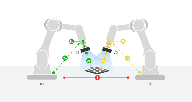
The overall process for dual robot relative pose calibration is shown in the figure below.

By default, Robot R2’s coordinate system is used as the reference frame. Cameras C1 and C2 are mounted on Robots R1 and R2, respectively. The pose of Robot R1 in Robot R2’s coordinate system is calculated. The steps are as follows:
-
Acquire EIH extrinsic parameters: Obtain the extrinsic parameters of Camera C1 on Robot R1 and Camera C2 on Robot R2 through hand-eye calibration. (See steps 2b and 3b in the figure)
-
Place and acquire calibration board images: Place the calibration board between the two robots, ensuring that it is visible to both cameras. Use Cameras C1 and C2 to independently acquire images and calculate the pose of the calibration board. The calibration board must remain stationary during image acquisition. If the calibration board moves, reacquire the images. (See steps 2c and 3c in the figure)
-
Enter flange poses: After image acquisition, record and manually enter the flange poses of Robots R1 and R2 at the moment the calibration board images were acquired. (See steps 2a and 3a in the figure)
-
Calculate relative pose: Based on the above data, calculate the relative pose of Robot R1 in Robot R2’s coordinate system. (See step 1 in the figure)
The following describes the pose calibration process in detail.
-
Acquire EIH extrinsic parameters for Robots R1 and R2.
Three methods are provided for acquiring EIH extrinsic parameters: Select from project, Acquire from EIH calibration, and Manually input. Details are shown in the table below.
No. Method Description 1
Select from project
-
If the calibration result of extrinsic parameters is already available, select the Project under the current solution.
-
Select the Calibration parameter group you need under the selected project.
-
The existing Calibration results will be loaded after selection.
2
Acquire from EIH calibration
Click Acquire from EIH calibration to open the 3D Camera Calibration tool, and refer to Hand-Eye Calibration Guide to acquire EIH extrinsic parameters.
3
Manually input
Click Manually input to open the pose editing tool, where EIH extrinsic parameters can be set manually.
After acquiring EIH extrinsic parameters, the calibration board poses captured by each robot need to be acquired separately, and the flange pose of each robot at the time of capture needs to be recorded.
-
-
Place and acquire calibration board images.
-
Select calibration board.
Set the standard calibration board model parameter in the parameter area, and then click the Next button.
-
Check calibration board position and image quality.
-
Place the calibration board in the shared area between the two robots, ensuring both cameras can capture it.
-
Click the Connect button to connect to the camera. Select the camera to be connected from the camera ID list, and then click the "Connect" icon to connect, or directly double-click the camera to connect.
-
Click the Acquire continuously button to acquire calibration board images. In the 2D interface, ensure that the calibration board within the red frame is complete. Also, check the quality of the calibration board image, which should meet the following requirements:
-
The overall calibration board in the 2D image should have balanced brightness, not too dark, too bright, or uneven. The calibration circles should be clear.
-
The calibration circles in the depth map should be intact.
If the image quality of the calibration board is poor, go to Mech-Eye Viewer and adjust the “calib” parameter group. If you are using DEEP or LSR series cameras, adjust the parameters under the "2D Image (Depth Source)" parameter group.
-
-
-
After confirming the calibration board position and image quality, keep the calibration board stationary. Click the Acquire image and calculate pose button to complete the calibration board pose acquisition and calculation.
-
Do not move the calibration board once its pose is determined. Robots R1 and R2 need to perform two image acquisitions respectively. If the calibration board moves during the acquisition process, return to the two "Acquire calibration board image and calculate pose" steps in the workflow to reacquire the images.
-
When acquiring calibration board images, accurately record the flange pose of the robot at the time of acquisition, and enter it in the subsequent steps. The entered flange pose must be exactly the same as the actual pose during image acquisition.
-
-
-
Enter the flange poses of Robots R1 and R2.
After acquiring and calculating the calibration board poses, enter the flange poses of Robots R1 and R2 recorded during calibration board image acquisition in the pose editing tool.
-
Calculate relative pose.
After successfully acquiring the above data, click the Calculate button to automatically calculate the relative pose relationship between the two robots, and the calculation result will be output through the output port.
-
Set the relative pose name.
In Basic settings, set the relative pose name for the robots, which will be used for reference within the solution. This name must not duplicate any existing relative pose name in the current solution.
The process of calibrating the relative pose with cameras mounted on two robots is now complete. Click the Apply button to complete the output port configuration and save the calibrated relative pose file.
Use the Calibrated Relative Pose Relationship between Two Robots
Load the calibrated dual robot relative pose relationship. This is applicable to scenarios where historical calibration results can be reused without repeating the calibration.
Select Creation Type
-
Click the Config wizard1 button to open the pose transformation tool and select Dual robot relative pose calibration.
-
In the parameter area on the right, select the creation type as Create from existing pose relationship, and select the existing robot-to-robot relationship under the current solution from the dropdown list.
-
Click the OK button. The calculation result and name of the existing dual robot relative pose relationship will be displayed.
-
After confirming the information is correct, click the Apply button to complete the output port configuration.
Typical Application Scenarios
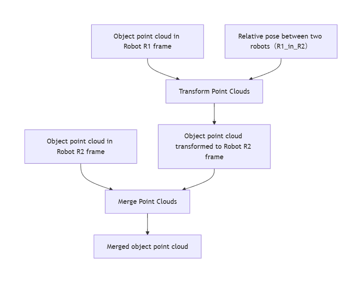
This function is commonly used in projects where point cloud or pose data collected by two robots need to be unified into the same robot reference frame. The typical usage procedure is as follows:

-
Calibration relative pose: Obtain the relative pose of the robot R1 in the R2 reference frame using the three methods described above.
-
Transform reference frame: Use the Transform Point Clouds or Transform Poses Step to transform the point cloud or pose data from Robot R1’s reference frame to Robot R2’s reference frame.
-
Merge data: Merge the point clouds or poses unified to Robot R2’s reference frame using Steps such as Merging Point Clouds or Merging Data for dual-robot collaboration.