Move Poses to Point Cloud Surfaces along Z-Axis

You are currently viewing the documentation for the latest version (2.2.0). To access a different version, click the "Switch version" button located in the upper-right corner of the page.

■ If you are not sure which version of the product you are currently using, please feel free to contact Mech-Mind Technical Support.

Function

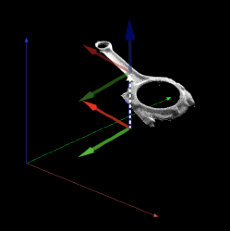
This Step moves poses along the Z-axis of a specified coordinate system to point cloud surfaces according to user-set rules.
function description

Usage Scenario

This Step is generally used to adjust poses that are not on object surfaces. Causes include tilted target objects and concave or convex surfaces. This Step is usually used after the Calc Poses and Dimensions from Planar Point Clouds Step.

Input and Output

Input

Input port Data type Description

Point Clouds

PointCloud/XYZNormal[]

Reference point clouds used to determine the Z-axis positions of poses.

Original Poses

Pose[]

A list of poses not yet moved to point cloud surfaces.

Output

Output port Data type Description

Adjusted Poses

Pose[]

A list of poses moved along the Z-axis to point cloud surfaces.

Parameter Description

Visualization Settings

Parameter Description

Show Point Cloud In Selected Frame

Description: Display point cloud under the robot reference frame or the camera reference frame.

Default value: Robot Coordinate

Value list: Robot Coordinate, Camera Coordinate

Instruction: When this parameter is set to Robot Coordinate, the Debug Output panel will display the visualized output under the camera reference frame; when it is set to Robot Coordinate, the panel will display the visualized output under the robot reference frame. Please refer to the tuning example for the corresponding result.

This parameter will appear only when the scene point cloud is set in the project.

  • Under the Robot Coordinate, the Debug Output panel is black, and you need to adjust the view to show the point cloud and coordinates.

  • Under the Camera Coordinate, the Debug Output panel only shows the point cloud, and you need to adjust point cloud orientation to show the coordinates.

Pose Type to Visualize

Description: This parameter is used to select the pose type to visualize.
Default value: After
Value list: After, Before, and All
Instruction: Select an appropriate option according to actual needs. Please refer to the tuning example for the corresponding result.

Cloud Capturing Settings

Parameter Description

Radius of XOY Plane

Parameter description: Set the distance from the pose origin to the search range boundary in the XOY plane, measured in millimeters (mm).
Default value: 5.000 mm.
Instruction: A larger radius expands the search range and may include more point cloud data. A smaller radius narrows the search range and may be more precise but might not find enough point cloud data.

Adjustment Settings

Parameter Description

Adjustment Settings

Parameter description: Set the algorithm or sorting mode for pose Z-axis movement.

Value list:

  • MinMaxZ: Sort by distance between poses and points in the Z direction. Select the point cloud with the maximum or minimum distance as the target.

  • CloudCenter: Sort poses according to their distances to the point cloud center, and select the point cloud with the best relative position as the target.

Instruction: Different adjustment settings will affect the options available in the “Reference Z-Axis” and “Select Z Value” parameters.

Reference Z Axis

Parameter description: Set the coordinate system reference for distance calculation.

Value list:

  • LocalZAxis: Use the Z-axis direction in the pose’s local coordinate system as reference. Position is calculated in the pose’s local coordinate system.

  • WorldZAxis: Use the Z-axis direction in the world coordinate system as reference. Position is calculated in the Z direction of the world coordinate system.

Instruction: This parameter is only available when "Adjustment Setting" is enabled. Selecting different reference coordinate systems affects the distance calculation results between poses and point clouds.

Calculation Settings

Parameter Description

Selected Z Value

Parameter description: Set the Z coordinate value selected from the point cloud as the target movement height for poses.

Value list:

  • MinZ: Select the minimum Z value from the point clouds within the search range.

  • MaxZ: Select the maximum Z value from the point clouds within the search range.

Instruction: Available options depend on the selection in "Adjustment Setting". The specific meaning of this parameter varies based on "Adjustment Setting" and "Reference Z Axis" settings.

Tuning Examples

Show Point Cloud In Selected Frame

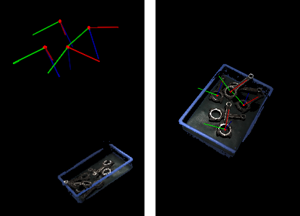
As shown below, the figure on the left shows the point cloud in the camera reference frame, and the figure on the right shows the point cloud in the robot reference frame.

transform poses transform poses

Pose Type to Visualize

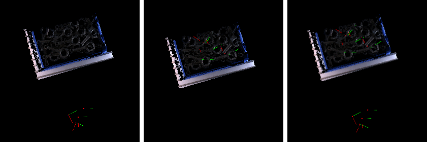
In the case of the robot reference frame, the visualized poses are as follows when the Pose Type to Visualize is set to After, Before, and All.

transform poses pose display settings

Is this page helpful?

You can give a feedback in any of the following ways:

We Value Your Privacy

We use cookies to provide you with the best possible experience on our website. By continuing to use the site, you acknowledge that you agree to the use of cookies. If you decline, a single cookie will be used to ensure you're not tracked or remembered when you visit this website.