Collision Detection
This section introduces settings relevant to collision detection.
Overview
In applications such as machine tending and (de)palletizing, avoiding collisions between the robot and the bin and other obstacles is crucial to keep the project running continuously. Mech-Viz can detect possible collisions and plan the robot path accordingly, so that the resulting path is collision-free. If a collision cannot be avoided, Mech-Viz will stop the project and display the detected collision in the 3D simulation area, so that you can adjust the project accordingly.
Collision Detection Configuration
To configure the following collision detection, click Collision detection configuration in the Collisions panel to open the Collision Detection Configuration window.
Collision occurs between two objects. Different sets of collision models can make up different collision detection combinations. By default, Mech-Viz detects collisions between the following objects: robot links - robot links, robot links - scene objects, robot links - robot tool, scene objects - robot tool. Additionally, you can configure point clouds, held workobjects, and more. Before you start the configuration, please add and configure the corresponding collision models in the project resource tree.
-
For adding and configuring the robot tool models, please refer to Tools.
-
For adding and configuring the scene object models, please refer to Scene objects.
-
The workobject models are automatically generated from the data provided by Mech-Vision. See below for detailed configuration instructions.
Collision between Point Cloud and Other Objects
Click the Detect collision between point cloud and others option in the Configuration on point cloud pane on the left to enable the detection of collisions between point cloud and the end tool. In addition, you can configure the detection of collisions between point cloud and robot links, and collisions between point cloud and held workobjects.
| Mech-Viz only detects collisions with point cloud for the “Vision Move” Step and the “Relative Move” Steps that depend on the “Vision Move” Step, but not for the other move-type Steps. |
-
Point cloud cube edge length
Point cloud cubes are the cubes centered at each point in the point cloud. If these cubes collide with other objects, the point cloud is considered to have collided with these objects.
Adjust the Point cloud cube edge length parameter according to the requirements of collision detection accuracy and speed. If you want to improve detection accuracy, you can decrease this parameter, but it will result in slower detection speed. Conversely, increasing this parameter can speed up detection but may reduce accuracy.
-
Point cloud collision calculation mode
It is recommended to use Full calculation during project debugging, and use Minimal calculation after the project is stable.
Option Description Minimal calculation
In this mode, the calculation speed is fast, but the information is not recorded completely. The collision volume reported in the plan history is not the final value, and point cloud that causes the collision is not recorded. Applicable for the production phase after the project is stable.
Full calculation
In this mode, the calculation speed is lower, but the complete information can be recorded. The collision volume reported in the plan history is the final volume. You can click on the corresponding item to view the point cloud that causes the collision. Applicable for project debugging.
Point Cloud and Tools
On the Configuration on tool pane, Collision volume threshold refers to the allowable collision volume between the point cloud cube and tool collision model. If the collision volume exceeds this threshold, a collision between the robot tool and point cloud is considered to have occurred.
Please adjust the Collision volume threshold parameter according to the actual tolerance of collision.
Point Cloud and Robot Links
On the Configuration on robot links pane, Collision volume threshold refers to the allowable collision volume between the point cloud cube and robot link model. If the collision volume exceeds this threshold, a collision between the robot tool and point cloud is considered to have occurred.
Robot links are divided into wrist, forearm, upper arm and base. By default, collisions between the robot links and point cloud are not detected.
Please enable the collision detection for robot links according to the actual requirements and adjust the Collision volume threshold parameter according to the actual tolerance of collision.
Collision between Held Workobject and Other Objects
Follow below steps to detect collisions between held workobjects and other objects. This option is mainly used for detecting collisions when moving the held workobject.
Please select Geometric solid or Custom model according to the model type of held workobject model.
Geometric Solid
Add Geometric Solid Models
Mech-Viz can generate collision models of cuboid and cylinder shapes based on the workobject dimensions provided by Mech-Vision. Therefore, please complete the following configurations in Mech-Vision to have the workobject dimensions output.
Configuration process:
-
In the Mech-Vision project, use either of the following Steps to obtain the workobject dimensions: Calc Poses and Dimensions from Planar Point Clouds: recommended for applications with multiple types of workobjects; Read Object Dimensions: recommended for applications with a single type of workobject.
-
Output the workobject dimensions with the “Procedure Out” Step. Then Mech-Viz can generate the corresponding collision models.
The number of output “pick point poses” and that of “object dimensions” should match.
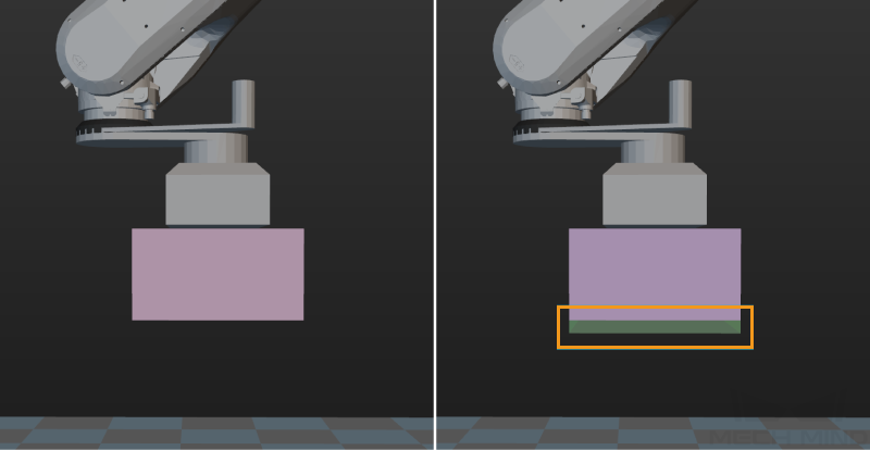
Bottom Safety Distance in Mixed-Case Palletizing
For mixed-case palletizing applications, please set an appropriate cuboid bottom safety distance for the cuboid workobject models. The cuboid bottom safety distance adds a collision detection zone to the bottom of the workobject model. If other objects enter this zone, these objects are considered to have collided with the workobjects. Setting a safety distance at the bottom of the cuboid can effectively avoid collisions between the placed workobjects and the held workobject that the robot is moving.
To set a cuboid bottom safety distance, enable Bottom safety distance in mixed-case palletizing, and then adjust the value of Cuboid bottom safety distance.
Collision Volume Threshold
Collision volume threshold refers to the allowable collision volume between the point cloud cube and held workobject model. If the collision volume exceeds this threshold, a collision between the robot tool and point cloud is considered to have occurred. To adjust this parameter, enable the Detect collision between point cloud and others option.
Please adjust this parameter according to the actual tolerance of collision.
Custom Model
Add Custom Models
Configuration process:
-
Move the STL and BINVOX model files of the workobject to the
collision_modelsfolder under the Mech-Viz project folder. If there is no collision_models folder, please create one yourself. -
Check the label name through the “Pose labels” port of the corresponding Step in Mech-Vision, and rename the model files to the label name. If you add a workobject configuration in the project resource tree of Mech-Viz, the workobject name must be the same as the label name.
-
In the “Send Point Cloud to External Service” Step of the corresponding Mech-Vision project, check the Send Object Information parameter and uncheck the Input Point Cloud in Camera Frame parameter. Connect all the input ports of this Step to the corresponding data flows.
| The output point cloud and pose must be in the robot reference frame. |
Collision Volume Threshold
Collision volume threshold refers to maximum allowable collision volume between the point cloud cube and held workobject model. If the collision volume between the held workobject model and the point cloud cubes exceeds this threshold, a collision will be detected. To adjust this parameter, enable the Detect collision between point cloud and others option.
Please adjust this parameter according to the actual tolerance of collision.
Collision Table Legend Description
-
[Gray Block] Collision will not be detected or collision will not occur.
-
[Blue Block] Consider collision detected when there is any contact.
-
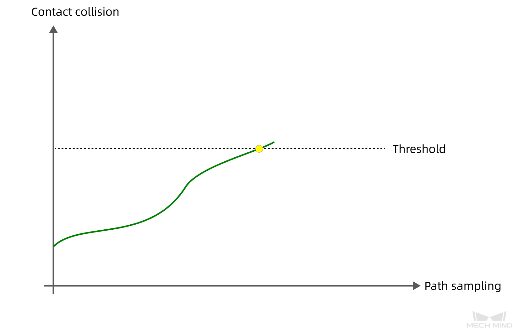
[Orange Block] Ignore collisions with contacts smaller than the configured volume threshold. Conversely, if the contact volume is larger than the configured volume threshold, a collision will be detected.
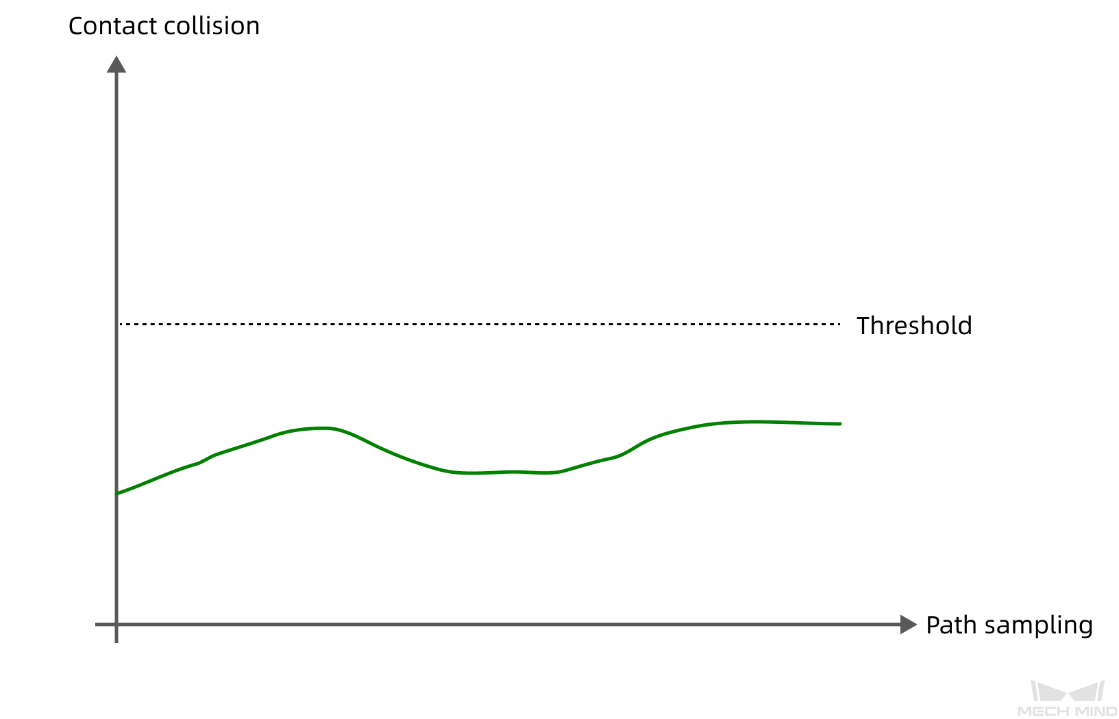
Contact volume remains below the configured volume threshold throughout the path sampling, no collision detected
Contact volume exceeds the configured volume threshold throughout the path sampling, collision detected
-
[Green Block] Consider collision detected when there is any object within bottom safety distance below held workobject(s).
-
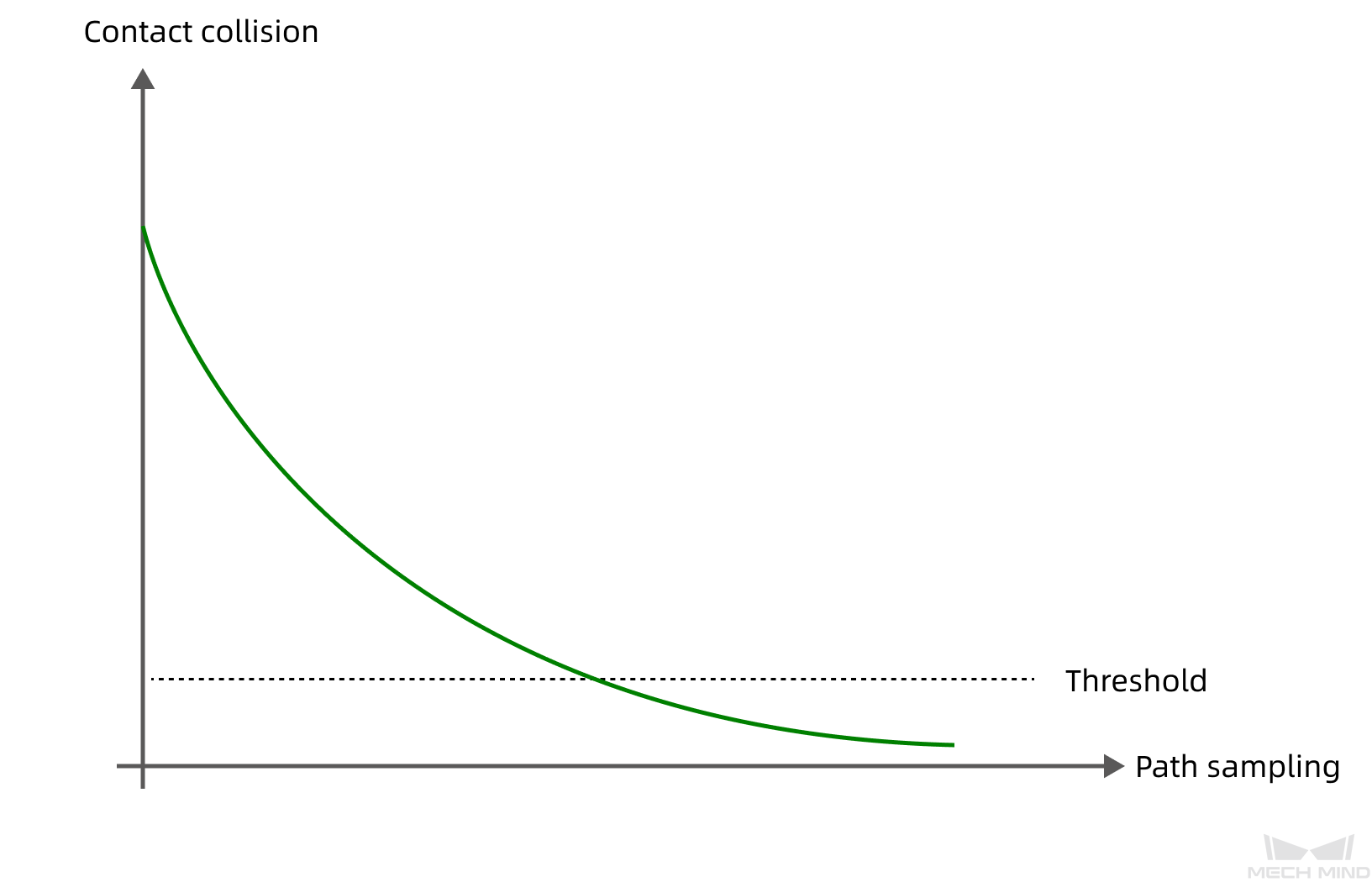
[Yellow Block] Ignore collisions with contacts that are larger than the configured volume threshold at first but the collision volumes gradually decrease, and collisions with contacts smaller than the configured volume threshold.
Although the contact volume exceeds the configured volume threshold, collisions whose contact volume shows a decreasing trend throughout the path sampling are allowed by the software.