Calc Hole Center Poses and Diameters
Function
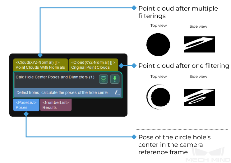
This Procedure is used to detect the circular hole and calculate the diameter of the circular hole and the pose of the circular hole’s center in the camera reference frame.
Usage Scenario
This Procedure is usually used in measurement scenarios for LARGE WORKPIECES. Usually, the Extract Planar Point Clouds Procedure is used before this Procedure to obtain the planar point cloud, and the Transform Poses to Custom Frame Procedure follows this Procedure to obtain the pose in the BASE REFERENCE FRAME.
Parameter Tuning
Detect and Measure Circle
- ROI
-
Parameter description: This parameter is used to set an ROI and read the center pose and size information of the circular hole.
Tuning recommendation: Please select an ROI in the Measurement Mode and set an accurate ROI.
|
When selecting an ROI, please make the selection frame as close to the circle as possible. An inaccurate ROI will affect the accuracy of the measured circle. |
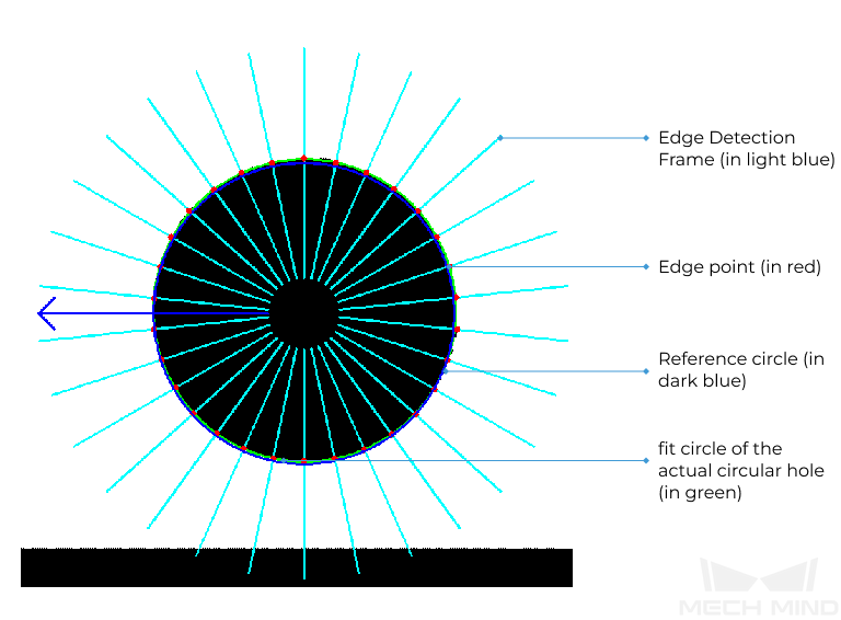
Principle: Once an ROI is determined with the selection frame, a reference circle with the center of the frame as the center and the short side of the frame as its diameter will be generated, and edge detection frames will be generated along the direction of the reference circle’s radius. Since the width of the edge detection frames are very small, they look like line segments, as shown below. In the edge detection frames, if the neighboring pixels change from black to white along the direction from the center outward, an edge point will be detected, and therefore a fit circle of the actual circular hole can be found with the detected edge points. The more the edge detection frames, the more the edge points and a more accurate circle can be calculated. The longer the length of the edge detection frame, the larger the detection area, and therefore even if the circle’s position changes in the image, it can still be accurately calculated.

-
Center X/Y: the coordinates of the circle’s center.
-
Width/Height: the actual size of the circle (diameter d in the figure below).
-
Angle: Set the rotation angle of the ROI selection frame.

- Number of Edge Detection Frames
-
Parameter description: This parameter specifies the number of edge detection frames of the measured circle. The larger the value, the more accurate the measured circle will be and the longer calculation time required.
Default value: 500
Tuning recommendation: If the circle is regular in shape, you can reduce the default value; if the circle is not regular, you can increase the default value.
- Edge Detection Frame Half Height
-
Parameter description: This parameter specifies the length of the edge detection frame. The longer the length of the edge detection frame, the larger the detection area, and the longer calculation time required . An overly large value may lead to an incorrect fit circle, because the single edge detection frame may have two intersections with the circle and unwanted edge points may be detected.
Default value: 110
Tuning recommendation: If the ROI can exactly enclose the entire circle (not applicable to semicircles), it is recommended to set this value to the radius of the circle, i.e., half of the width/height in ROI. If the ROI cannot enclose the entire circle or there are other edges in the image, please set the value according to the actual situation.
Extract 3D Points in Cylinder
|
When this Procedure is executed, the point cloud will be converted from the camera reference frame to the point’s reference frame. The following parameters are used to set the range of the Z coordinates in the point’s reference frame. |
- Min Z Value
-
Parameter description: This parameter specifies the minimum value (unit: mm) of the Z coordinate in the point’s reference frame. The smaller the value, more points will be extracted.
Default value: −0.500 mm
- Max Z Value
-
Parameter description: This parameter specifies the maximum value (unit: mm) of the Z coordinate in the point’s reference frame. The larger the value, more points will be extracted.
Default value: 0.500 mm
