AUBO(ARCS) Standard Interface Commands
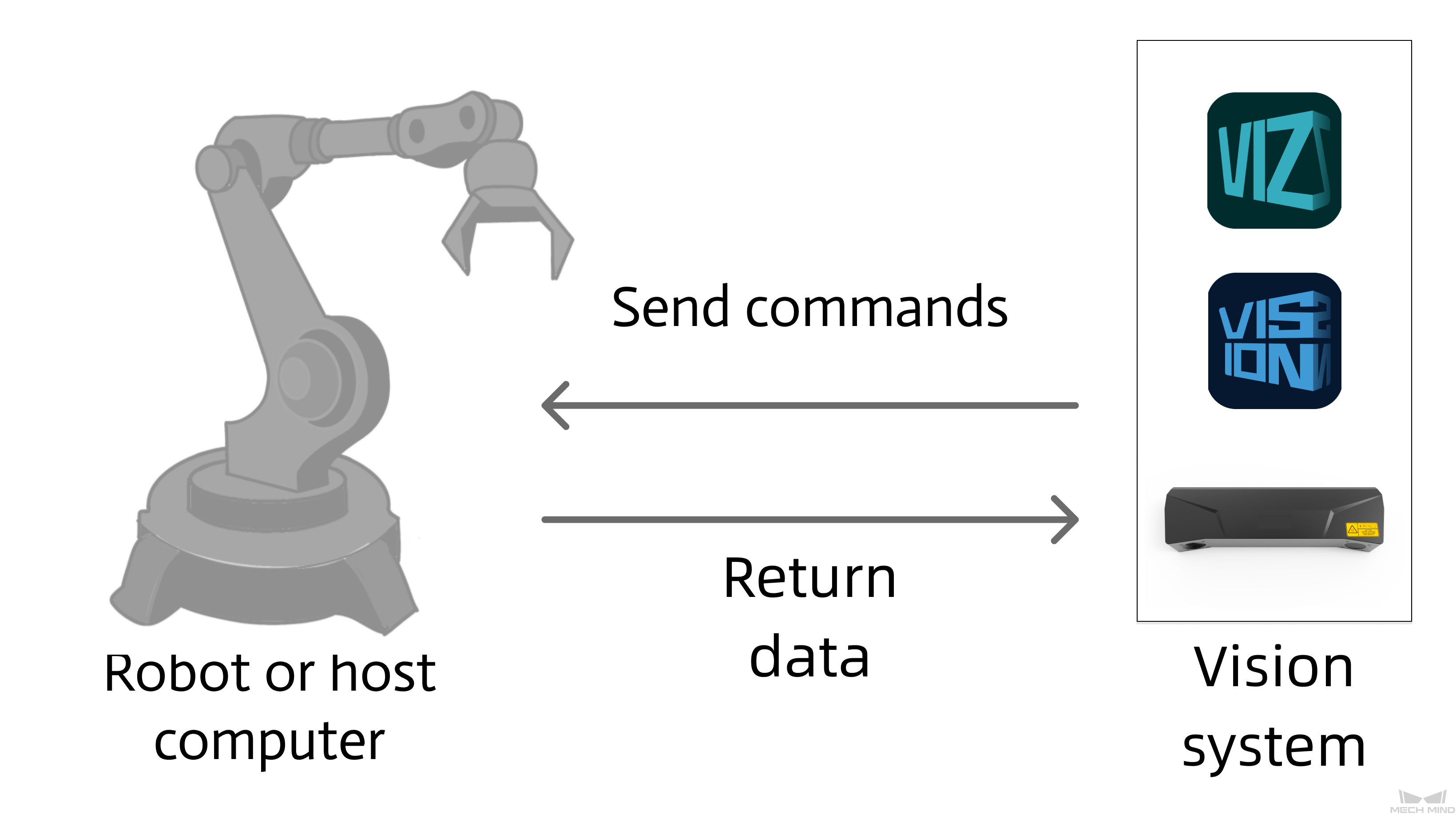
This section describes standard interface commands used in TCP communications between a AUBO(ARCS) robot and Mech-Mind Vision System. The robot (the client) sends commands to Mech-Mind Vision System (the server), and Mech-Mind Vision System returns the processed data to the robot.
Notes
-
When programming a AUBO(ARCS) robot, take note of the following items:
-
g_mm_status(global variable): The variable that stores the command execution status code. The user can check the value of this variable after calling the relevant instructions to determine whether the execution is successful or handle abnormal situations.
-
For the instruction names described below, the name outside the parentheses is the short name, and the name inside the parentheses is the full name. For example, initSocket(mm_init_socket), where initSocket is the short name and mm_init_socket is the full name.
-
-
Unit of data:
-
The unit of joint positions is degree (°).
-
The robot flange pose or robot tool pose is represented in six dimensions, denoted as [x, y, z, a, b, c].
-
The position components x, y, and z in the pose are measured in millimeters (mm).
-
The orientation components a, b, and c in the pose are represented as Euler angles, with units in degrees (°).
-
The format of the Euler angles for the input flange pose corresponds to the selected robot brand. If another robot brand is selected in the communication configuration, the corresponding Euler angle convention must be chosen.
-
-
Vision point and waypoint:
-
Vision point: An object recognized by Mech-Vision. A vision point has information including the object pose, label, dimensions, and custom data.
-
Waypoint: Each point that the robot reaches when moving along the planned path. A waypoint has information including the robot pose, label, and motion type. Waypoints can be divided into two categories:
-
Vision Move waypoint: Waypoint corresponding to the Vision Move Step.
-
Non-Vision Move waypoints, which refer to the waypoints corresponding to Move-type Steps other than the Vision Move Step.
-
-
Initialize Communication
Description
This command sets the IP address of the IPC, port number, and timeout period for robot communication.
Calling Sequence
-
This instruction must be called in the before “Establish the communication” section.
-
To establish the communication between the robot and the vision system, call openSkt after this command.
Command
initSocket(mm_init_socket)Input Parameters
IP
This parameter specifies the string-type IP address of the IPC.
Port
This parameter specifies the port number used by the IPC to establish the communication between the IPC and the robot. This port number must be consistent with the host port number that is specified for robot communication in the toolbar of Mech-Vision.
TimeOut
This parameter specifies the communication timeout period. Unit: seconds. This parameter is built-in; the user does not need to set it.
Establish TCP Communication
This command establishes the TCP communication between the robot and the vision system.
Calling Sequence
This instruction must be called after the initSocket instruction.
Run Mech-Vision Project
Description
This command triggers the Mech-Vision project to run. When the Mech-Vision project is running, the vision system triggers the camera to capture images and then process the returned images with algorithms to produce a series of vision points or waypoints.
|
Calling Sequence
-
The step parameters of the project must be configured before running the Mech-Vision project; therefore, the addFunc instruction with the mm_set_model parameter or the addFunc instruction with the mm_set_boxsize parameter must be called before the startVis instruction.
-
Vision system gets vision points and waypoints only after a Mech-Vision project runs. Therefore, call startVis before calling getData.
Command
startVis(mm_start_vision)Input Parameters
Project ID
Mech-Vision project ID. You can view the project ID of a Mech-Vision project in the Project List section of Mech-Vision. The project ID is the number before the project name.
PosNumberNeed
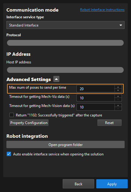
This parameter specifies the number of vision points or waypoints expected to be returned by the Mech-Vision project. Valid values: 0 to the largest positive integer.
| If the Mech-Vision project has a Path Planning Step, this parameter indicates the expected number of waypoints. Otherwise, it indicates the expected number of vision points. |
-
0: Obtain all vision points or waypoints from the Mech-Vision project.
-
A positive integer: Obtain the specific number of vision points or waypoints from the Mech-Vision project.
-
If the total amount of vision points or waypoints output by the Mech-Vision project is smaller than the parameter value, this command will obtain the number of all vision points or waypoints.
-
If the total amount of vision points or waypoints output by the Mech-Vision project is larger than or equal to the parameter value, this command will obtain the number of vision points or waypoints as specified by this parameter.
-
|
Type of robot pose to send
This parameter specifies the pose type of the real robot to send to the Mech-Vision project. Mech-Vision Valid values: None, Current Position, Current Flange Pose, Predefined Jps. The following table describes the details.
| Type of robot pose to send | Description | Application scenario |
|---|---|---|
None |
The command does not send the robot pose to the Mech-Vision project. If the Path Planning Step is used in the Mech-Vision project, the start point of the planned path will be the Home point set in the path planning tool. |
This setting should be used if the camera is mounted in eye to hand mode and the project does not require images to be captured beforehand. |
Current Position |
The current joint positions and flange pose of the robot must be input to the Mech-Vision project. |
This setting should be used when the camera is mounted in eye in hand mode. This setting is recommended for most scenarios except those involving gantry robots. |
Current Flange Pose |
The robot flange pose must be input to the Mech-Vision project. |
This setting is recommended for scenarios involving gantry robots. |
Predefined Jps |
This command sends custom joint positions to the Mech-Vision project. These joint positions will be sent to the Path Planning Step in the Mech-Vision project as the start point, where the robot will move from this start point to the first waypoint of the planned path.
|
This setting should be used if the camera is mounted in eye to hand mode and the project requires images to be captured beforehand. |
Predefined Jps
This parameter specifies the custom joint position data.
-
If the Type of robot pose to send parameter is set to Predefined Jps, the joint positions will be sent to the Path Planning Step in the Mech-Vision project as the start point, where the robot moves from this start point to the first waypoint of the planned path.
-
If the Type of robot pose to send parameter is not set to Predefined Jps, the Predefined Jps field is automatically populated with a default value; no manual configuration is required.
Retrieve Data
Command
getData(mm_get_data)Parameter Description
None (do not retrieve data)
This parameter indicates that no data will be retrieved from Mech-Vision or Mech-Viz outputs.
From Vision (retrieve Mech-Vision output data)
mm_get_vis_data (obtain the vision result)
Description
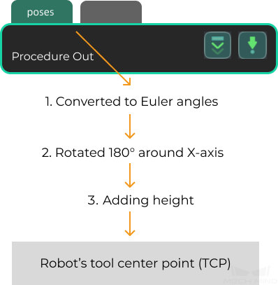
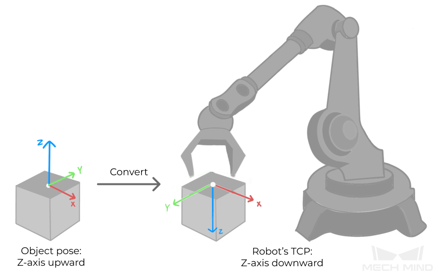
Select mm_get_vis_data to retrieve the Viz output (a series of vision points), obtaining each point’s pose, label, and end effector. The object pose of the vision point (namely, the output of the poses port of the Output Step) will be automatically converted to the robot’s TCP by the vision system. The process is as follows.
| If the first input port of the Output Step is Object Center Points, the Output Step will convert the object center points into the corresponding pick points. Therefore, the object poses obtained by running this command are actually poses of pick points, instead of poses of object center points. |
-
Convert the object pose from a quaternion to Euler angles.
-
Rotate the object’s pose around the X-axis by 180° to orient its Z-axis downward.
Calling Sequence
The execution result of this instruction is temporarily stored in the robot’s memory. The user must then call getPosejps (with the mm_get_pos parameter) to transfer the data before it can be accessed.
Input Parameters
- Project ID
-
Mech-Vision project ID. You can view the project ID of a Mech-Vision project in the Project List section of Mech-Vision. The project ID is the number before the project name.
Output Parameters
- Pose Num
-
This parameter specifies a variable name. This parameter stores the number of vision points returned by Mech-Vision.
- g_mm_status
-
This parameter indicates the name of the variable for storing the command execution status code. Status code 1100 is returned for a successful command execution. If a command fails to be run, a specific error code is returned. For details, see Status Codes and Troubleshooting.
mm_get_dy_data (Get Mech-Vision Custom Data)
Description
Select mm_get_dy_data, in addition to the vision points’ poses and labels, the custom port data from the “Output” step.
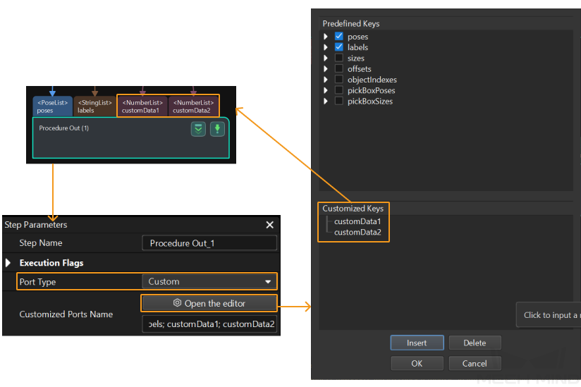
Select the Output Step, set Port Type to Custom, and then click Open the editor to go to the custom port configuration window. The Customized Keys section of the window displays custom port names, such as customeData1 and customeData2 as shown in the following figure.
|
Calling Sequence
The execution result of this instruction is temporarily stored in the robot’s memory. The user must then call getPosejps (with the mm_get_dypos) to transfer the data before it can be accessed.
Input Parameters
- Project ID
-
Mech-Vision project ID. You can view the project ID of a Mech-Vision project in the Project List section of Mech-Vision. The project ID is the number before the project name.
Output Parameters
- Pose Num
-
This parameter specifies a variable name. This parameter stores the number of vision points returned by Mech-Vision.
- g_mm_status
-
This parameter indicates the name of the variable for storing the command execution status code. Status code 1100 is returned for a successful command execution. If a command fails to be run, a specific error code is returned. For details, see Status Codes and Troubleshooting.
mm_get_vis_path (obtain the planned path from Mech-Vision)
Description
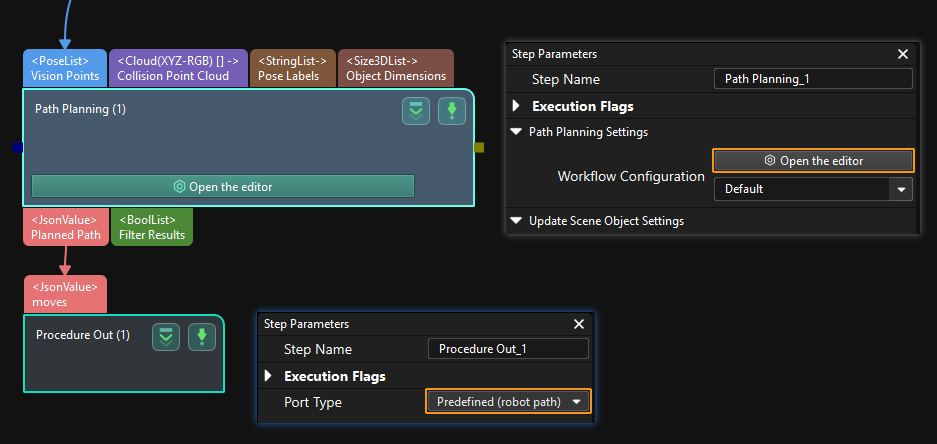
Select mm_get_vis_path to retrieve the Mech-Vision planned path (a series of waypoints), obtaining each pose of waypoint, label, and end effector. The path is planned by the path planning tool, which you may enter by clicking Config wizard as shown in the image below. For details about Path Planning, see Path Planning.
| Set the Port Type parameter of the Output Step in Mech-Vision to Predefined (robot path). |
Calling Sequence
The execution result of this instruction is temporarily stored in the robot’s memory. The user must then call getPosejps (with the mm_get_pos parameter) to transfer the data before it can be accessed.
-
mm_get_pos parameter: The pose is in tool pose (TCP) format.
-
mm_get_jps parameter: The pose is in joint format.
Input Parameters
- Project ID
-
Mech-Vision project ID. You can view the project ID of a Mech-Vision project in the Project List section of Mech-Vision. The project ID is the number before the project name.
- Pose Type
-
This parameter specifies the type of waypoint poses to be obtained. Valid values: 1 and 2.
-
1: Joint positions.
-
2: TCP.
-
Output Parameters
- Pose Num
-
This parameter specifies a variable name. This parameter stores the number of vision points returned by Mech-Vision.
- Vision Pose Index
-
This parameter specifies a variable name. This parameter indicates the sequence number of the Vision Move waypoint corresponding to the “Vision Move” Step of the path planning tool in the entire path. If the path does not contain a “Vision Move” waypoint, the value of this parameter is 0.
For example, if the planned path consists of the following waypoints: "Fixed-Point Move_1", "Fixed-Point Move_2", "Vision Move", "Fixed-Point Move_3", the sequence number of the Vision Move waypoint is 3.
- g_mm_status
-
This parameter indicates the name of the variable for storing the command execution status code. Status code 1103 is returned for a successful command execution. If a command fails to be run, a specific error code is returned. For details, see Status Codes and Troubleshooting.
mm_get_plan_data (obtain the Mech-Vision planned path)
Description
Set Result Type to mm_get_plan_data to indicate that, in addition to obtaining the planned path from the Mech-Vision project, Vision Move data or custom data is also obtained. “Vision Move data” refers to data output by the Vision Move Step in the path planning tool, which you may enter from the Path Planning Step. Vision Move data includes labels of picked target objects, number of picked target objects, number of target objects to be picked this time, edge/corner ID of vacuum gripper, TCP offset, orientation of target object group, orientation of target object, and dimensions of target object group.
Calling Sequence
The execution result of this instruction is temporarily stored in the robot’s memory. The user must then call getPosejps (with the mm_get_pos parameter) to transfer the data before it can be accessed.
Input Parameters
- Project ID
-
Mech-Vision project ID. You can view the project ID of a Mech-Vision project in the Project List section of Mech-Vision. The project ID is the number before the project name.
- Pose Type
-
This parameter specifies the type of waypoint poses to be obtained. Valid values: 1 and 2.
-
1: Joint positions.
-
2: TCP.
-
Output Parameters
- Pose Num
-
This parameter specifies a variable name. This parameter stores the number of vision points returned by Mech-Vision.
- Vision Pose Index
-
This parameter specifies a variable name. This parameter indicates the sequence number of the Vision Move waypoint corresponding to the “Vision Move” Step of the path planning tool in the entire path. If the path does not contain a “Vision Move” waypoint, the value of this parameter is 0.
For example, if the planned path consists of the following waypoints: "Fixed-Point Move_1", "Fixed-Point Move_2", "Vision Move", "Fixed-Point Move_3", the sequence number of the Vision Move waypoint is 3.
- g_mm_status
-
This parameter indicates the name of the variable for storing the command execution status code. Status code 1103 is returned for a successful command execution. If a command fails to be run, a specific error code is returned. For details, see Status Codes and Troubleshooting.
From Vision (retrieve Mech-Viz output data)
mm_get_viz_data (obtain the path planned by Mech-Viz)
Description
Select mm_get_viz_data to retrieve the Mech-Viz planned path (a series of waypoints), obtaining each pose of waypoint, label, and end effector.
Calling Sequence
The execution result of this instruction is temporarily stored in the robot’s memory. The user must then call getPosejps (with the mm_get_pos parameter) to transfer the data before it can be accessed.
-
mm_get_pos parameter: The pose is in tool pose (TCP) format.
-
mm_get_jps parameter: The pose is in joint format.
Input Parameters
- Pose Type
-
This parameter specifies the type of waypoint poses to be obtained. Valid values: 1 and 2.
-
1: Joint positions.
-
2: TCP.
-
Output Parameters
- Pose Num
-
This parameter specifies a variable name. This parameter stores the number of vision points returned by Mech-Viz.
- Vision Pose Index
-
This parameter specifies a variable name. This parameter specifies the sequence number of the Vision Move waypoint (i.e., the waypoint corresponding to the “Vision Move” Step in the Mech-Viz project) in the planned path. If the path does not contain a “Vision Move” waypoint, the value of this parameter is 0.
For example, if the planned path consists of the following waypoints: "Fixed-Point Move_1", "Fixed-Point Move_2", "Vision Move", "Fixed-Point Move_3", the sequence number of the Vision Move waypoint is 3.
- g_mm_status
-
This parameter indicates the name of the variable for storing the command execution status code. Status code 2100 is returned for a successful command execution. If a command fails to be run, a specific error code is returned. For details, see Status Codes and Troubleshooting.
mm_get_plan_data (obtain the planned path from the Mech-Viz project, Vision Move data or custom data is also obtained)
Description
Set Result Type to mm_get_plan_data to indicate that, in addition to obtaining the planned path from the Mech-Viz project, Vision Move data or custom data is also obtained.
-
Vision Move data refers to data output by the Vision Move Step in Mech-Viz, including the labels of picked workobjects, number of picked workobjects, number of workobjects to be picked this time, edge or corner ID of vacuum gripper, TCP offset, orientation of workobject group, orientation of workobject, and dimensions of workobject group.
-
Custom data: Refers to data output by the custom-type port(s) of the “Output” Step in Mech-Vision and then forwarded by Mech-Viz.
Select the Output Step, set Port Type to Custom, and then click Open the editor to go to the custom port configuration window. The Customized Keys section of the window displays custom port names, such as customeData1 and customeData2 as shown in the following figure.
-
Data output from Predefined Keys, such as poses, labels, sizes, offsets, is not custom data.
-
You must set Port Type of the Output Step to Custom and select the poses port in the Predefined Keys section in Mech-Vision.
-
Calling Sequence
The execution result of this instruction is temporarily stored in the robot’s memory. The user must then call getPosejps (with the mm_get_pos parameter) to transfer the data before it can be accessed.
-
mm_get_pos parameter: The pose is in tool pose (TCP) format.
-
mm_get_jps parameter: The pose is in joint format.
Input Parameters
- Project ID
-
This parameter must be set to 0.
- Pose Type
-
This parameter specifies the data format returned by Mech-Viz; valid values are 1, 2, 3, or 4.
Pose Type
Description of expected returned data (Each field is explained below. If the Mech-Vision project does not have a custom port, no elements of custom data are returned.)
Waypoint type
Data
1
Non-Vision Move waypoint
Pose (JPs), motion type, tool ID, velocity
Vision Move waypoint
Pose (joint positions), motion type, tool ID, velocity, element 1 in custom data, … element N in custom data
2
Non-Vision Move waypoint
Pose (TCP), motion type, tool ID, velocity
Vision Move waypoint
Pose (TCP), motion type, tool ID, velocity, element 1 in custom data, … element N in custom data
3
Non-Vision Move waypoint
Pose (JPs), motion type, tool ID, velocity
Vision Move waypoint
Pose (joint positions), motion type, tool ID, velocity, Vision Move data, element 1 in custom data, … element N in custom data
4
Non-Vision Move waypoint
Pose (TCP), motion type, tool ID, velocity
Vision Move waypoint
Pose (TCP), motion type, tool ID, velocity, Vision Move data, element 1 in custom data, … element N in custom data
- Pose
-
The pose type of the waypoints can be robot’s joint positions or TCP, depending on the value of Pose Type.
- Motion type
-
-
1: Joint motion (MOVEJ)
-
2: Linear motion (MOVEL)
-
- Tool ID
-
The ID of the tool to be used at this waypoint. A value of -1 means that no tool is used at this waypoint.
- Velocity
-
The parameter value, represented in percentage, equals the velocity set for the move-type Steps multiplied by the global velocity set in Mech-Viz.
- Vision Move data
-
Data output by the Vision Move Step in Mech-Viz, including labels of picked target objects, number of picked target objects, number of target objects to be picked this time, edge or corner ID of vacuum gripper, TCP offset, orientation of target object group, orientation of target object, and dimensions of target object group.
Name Description Number of Elements Labels of picked target objects
A label consists of 10 integers. The default value is ten 0s.
10
Number of picked target objects
The total number of picked target objects.
1
The number of target objects to be picked this time.
The number of target objects to be picked this time.
1
Edge or corner ID of vacuum gripper
The ID of the edge or corner used to pick target objects this time.
1
TCP offset
The XYZ offset between the center of the target object group and the tool pose center.
3
Orientation of target object group
The relative position between the target object group and the length of the vacuum gripper. The value is 0 or 1, where 0 stands for parallel and 1 for vertical.
1
Orientation of target object
The relative position between the length of a target object and that of the vacuum gripper. The value is 0 or 1, where 0 stands for parallel and 1 for vertical
1
Dimensions of target object group
The length, width, and height of the target object group to be picked this time
3
- Element in custom data
-
The data of all custom ports of a single vision point. For example, data output from ports of the “Output” Step is presented in the following table. The elements in custom data of the first waypoint are [0, 0, 1] and [0, 0]; and the elements in custom data of the second waypoint are [1, 0, 0] and [1, 1].
Port name
poses
labels
customData1
customData2
Output data
[
[0, 0, 0, 1, 0, 0, 0],
[0, 0, 0, 1, 0, 0, 0]
]
[
"0",
"1"
]
[
[0, 0, 1],
[1, 0, 0]
]
[
[0, 0],
[1, 1]
]
First waypoint
[0, 0, 0, 1, 0, 0, 0]
0
[0, 0, 1]
[0, 0]
Second waypoint
[0, 0, 0, 1, 0, 0, 0]
1
[1, 0, 0]
[1, 1]
Output Parameters
- Pose Num
-
This parameter specifies a variable name. This parameter stores the number of vision points returned by Mech-Viz.
- Vision Pose Index
-
This parameter specifies a variable name. This parameter specifies the sequence number of the Vision Move waypoint (i.e., the waypoint corresponding to the “Vision Move” Step in the Mech-Viz project) in the planned path. If the path does not contain a “Vision Move” waypoint, the value of this parameter is 0.
For example, if the planned path consists of the following waypoints: "Fixed-Point Move_1", "Fixed-Point Move_2", "Vision Move", "Fixed-Point Move_3", the sequence number of the Vision Move waypoint is 3.
- g_mm_status
-
This parameter indicates the name of the variable for storing the command execution status code. Status code 2100 is returned for a successful command execution. If a command fails to be run, a specific error code is returned. For details, see Status Codes and Troubleshooting.
Store the data
Description
This command stores the data of the vision point or waypoint in the variables.
Calling Sequence
This instruction must be called after the getData instruction.
Command
getPosejps(mm_get_posjps)Parameter Description
None (Do not store data)
This parameter indicates that no data is stored.
mm_get_pos (stores vision results or planned paths; the pose is represented in tool pose format)
Description
The mm_get_pos command stores the TCP, label, and tool ID of the vision point or waypoint in the variables.
Input Parameters
- Index
-
This parameter specifies the index of the vision point or waypoint. The TCP, label, and tool ID of the vision point or waypoint that corresponds to the index are stored in the variables. Indexes start from 1.
Output Parameters
- Pose
-
This parameter specifies a variable name. This parameter stores the TCP of the vision point or waypoint that corresponds to the index.
- Tool ID
-
This parameter specifies a variable name. This parameter stores the tool ID of the vision point or waypoint that corresponds to the index.
- Label
-
This parameter specifies a variable name. This parameter stores the label of the vision point or waypoint that corresponds to the index.
mm_get_jps (stores vision results or planned paths; the pose is represented in joint format)
Description
The mm_get_jps command stores the joint positions, label, and tool ID of the waypoint in the variables.
Input Parameters
- Index
-
This parameter specifies the index of the waypoint. The joint positions, label, and tool ID of the waypoint that corresponds to the index are stored in the variables. Indexes start from 1.
Output Parameters
- Jps
-
This parameter specifies a variable name. This parameter stores the joint positions of the waypoint that corresponds to the index.
- Tool ID
-
This parameter specifies a variable name. This parameter stores the tool ID of the waypoint that corresponds to the index.
- Label
-
This parameter specifies a variable name. This parameter stores the label of the waypoint that corresponds to the index.
mm_get_dypos (stores Mech-Vision custom data)
Description
The mm_get_dypos command stores the TCP, label, and custom data of the vision point or waypoint in the variables.
Input Parameters
- Index
-
This parameter specifies the index of the vision point. The custom data of the vision point that corresponds to the index is stored in the variable. Indexes start from 1.
Output Parameters
- Pose
-
This parameter specifies a variable name. This parameter stores the TCP of the vision point that corresponds to the index.
- Label
-
This parameter specifies a variable name. This parameter stores the label of the vision point that corresponds to the index. If no label information is available, the label value defaults to 0.
- Custom Data
-
This parameter specifies a variable name. This parameter stores the custom data of the vision point that corresponds to the specified index. For example, data output from ports of the Output Step is presented in the following table. The elements in custom data of the first vision point are [0, 0, 1] and [0, 0]; and the elements in custom data of the second vision point are [1, 0, 0] and [1, 1].
Port name
poses
labels
customData1
customData2
Output data
[
[0, 0, 0, 1, 0, 0, 0],
[0, 0, 0, 1, 0, 0, 0]
]
[
"0",
"1"
]
[
[0, 0, 1],
[1, 0, 0]
]
[
[0, 0],
[1, 1]
]
First vision point
[0, 0, 0, 1, 0, 0, 0]
0
[0, 0, 1]
[0, 0]
Second vision point
[0, 0, 0, 1, 0, 0, 0]
1
[1, 0, 0]
[1, 1]
mm_get_plan_pos (stores vision results or planned paths; the pose is represented in tool pose format)
Description
The mm_get_plan_pos command stores the tool pose, motion type, tool ID, speed, custom data, and planned paths of a waypoint into the specified variables.
Input Parameters
- Index
-
This parameter specifies the index the waypoint. The tool pose, motion type, tool ID, speed, custom data, and planned paths that corresponds to the index is stored in the variables. Indexes start from 1.
Output Parameters
- Pose
-
This parameter specifies a variable name. This parameter stores the TCP of the waypoint that corresponds to the index.
- Move Type
-
This parameter specifies a variable name. This parameter stores the Vision Move data of the waypoint that corresponds to the index, valid values are 1 or 2.
-
1: Joint motion (MOVEJ)
-
2: Linear motion (MOVEL)
-
- Tool ID
-
This parameter specifies a variable name. This parameter stores the tool ID of the waypoint that corresponds to the index. A value of -1 means that no tool is used at this waypoint.
- Speed
-
This parameter specifies a variable name. This parameter stores the velocity of the waypoint that corresponds to the index. The meaning of velocity varies based on the project type.
-
For Mech-Vision projects, velocity indicates the Simulation Speed value in the path planning tool, in the form of percentage.
-
For Mech-Viz projects, velocity, represented in percentage, indicates the velocity set for a move-type Step multiplied by the global velocity set in Mech-Viz.
-
- Custom Data
-
This parameter specifies a variable name. This parameter stores the custom data of the waypoint that corresponds to the index. For example, data output from ports of the “Output” Step is presented in the following table. The elements in custom data of the first waypoint are [0, 0, 1] and [0, 0]; and the elements in custom data of the second waypoint are [1, 0, 0] and [1, 1].
Port name
poses
labels
customData1
customData2
Output data
[
[0, 0, 0, 1, 0, 0, 0],
[0, 0, 0, 1, 0, 0, 0]
]
[
"0",
"1"
]
[
[0, 0, 1],
[1, 0, 0]
]
[
[0, 0],
[1, 1]
]
First waypoint
[0, 0, 0, 1, 0, 0, 0]
0
[0, 0, 1]
[0, 0]
Second waypoint
[0, 0, 0, 1, 0, 0, 0]
1
[1, 0, 0]
[1, 1]
- Plan Data
-
This parameter specifies a variable name. This parameter stores the Vision Move data of the waypoint that corresponds to the index. The following table details Vision Move data.
Name Description Number of Elements Labels of picked target objects
A label consists of 10 integers. The default value is ten 0s.
10
Number of picked target objects
The total number of picked target objects.
1
The number of target objects to be picked this time.
The number of target objects to be picked this time.
1
Edge or corner ID of vacuum gripper
The ID of the edge or corner used to pick target objects this time.
1
TCP offset
The XYZ offset between the center of the target object group and the tool pose center.
3
Orientation of target object group
The relative position between the target object group and the length of the vacuum gripper. The value is 0 or 1, where 0 stands for parallel and 1 for vertical.
1
Orientation of target object
The relative position between the length of a target object and that of the vacuum gripper. The value is 0 or 1, where 0 stands for parallel and 1 for vertical
1
Dimensions of target object group
The length, width, and height of the target object group to be picked this time
3
mm_get_plan_jps (stores vision results or planned paths; the pose is represented in joint format)
Description
The mm_get_plan_jps command stores the tool pose, motion type, tool ID, speed, custom data, and planned paths of a waypoint into the specified variables.
Input Parameters
- Index
-
This parameter specifies the waypoint index; it stores into the specified variables the joint angles, motion type, tool ID, speed, custom data, and planned path of the waypoint corresponding to that index. Indexes start from 1.
Output Parameters
- Pose
-
This parameter specifies a variable name. This parameter stores the joint positions of the waypoint that corresponds to the index.
- Move Type
-
This parameter specifies a variable name. This parameter stores the Vision Move data of the waypoint that corresponds to the index, valid values are 1 or 2.
-
1: Joint motion (MOVEJ)
-
2: Linear motion (MOVEL)
-
- Tool ID
-
This parameter specifies a variable name. This parameter stores the tool ID of the waypoint that corresponds to the index. A value of -1 means that no tool is used at this waypoint.
- Speed
-
This parameter specifies a variable name. This parameter stores the velocity of the waypoint that corresponds to the index. The meaning of velocity varies based on the project type.
-
For Mech-Vision projects, velocity indicates the Simulation Speed value in the path planning tool, in the form of percentage.
-
For Mech-Viz projects, velocity, represented in percentage, indicates the velocity set for a move-type Step multiplied by the global velocity set in Mech-Viz.
-
- Custom Data
-
This parameter specifies a variable name. This parameter stores the custom data of the waypoint that corresponds to the index. For example, data output from ports of the “Output” Step is presented in the following table. The elements in custom data of the first waypoint are [0, 0, 1] and [0, 0]; and the elements in custom data of the second waypoint are [1, 0, 0] and [1, 1].
Port name
poses
labels
customData1
customData2
Output data
[
[0, 0, 0, 1, 0, 0, 0],
[0, 0, 0, 1, 0, 0, 0]
]
[
"0",
"1"
]
[
[0, 0, 1],
[1, 0, 0]
]
[
[0, 0],
[1, 1]
]
First waypoint
[0, 0, 0, 1, 0, 0, 0]
0
[0, 0, 1]
[0, 0]
Second waypoint
[0, 0, 0, 1, 0, 0, 0]
1
[1, 0, 0]
[1, 1]
- Plan Data
-
This parameter specifies a variable name. This parameter stores the Vision Move data of the waypoint that corresponds to the index. The following table details Vision Move data.
Name Description Number of Elements Labels of picked target objects
A label consists of 10 integers. The default value is ten 0s.
10
Number of picked target objects
The total number of picked target objects.
1
The number of target objects to be picked this time.
The number of target objects to be picked this time.
1
Edge or corner ID of vacuum gripper
The ID of the edge or corner used to pick target objects this time.
1
TCP offset
The XYZ offset between the center of the target object group and the tool pose center.
3
Orientation of target object group
The relative position between the target object group and the length of the vacuum gripper. The value is 0 or 1, where 0 stands for parallel and 1 for vertical.
1
Orientation of target object
The relative position between the length of a target object and that of the vacuum gripper. The value is 0 or 1, where 0 stands for parallel and 1 for vertical
1
Dimensions of target object group
The length, width, and height of the target object group to be picked this time
3
Run Mech-Viz Project
Description
This command triggers the Mech-Viz project to run. Mech-Viz plans a path for the robot based on the vision results output by Mech-Vision.
| Right-click the project name in the project resource panel in Mech-Viz and select Autoload Project. |
Calling Sequence
The step parameters of the project must be configured before running the Mech-Viz project; therefore, the addFunc instruction with the mm_set_model parameter or the addFunc instruction with the mm_set_boxsize parameter must be called before the startVis instruction.
Command
startViz(mm_start_viz)Input Parameters
Type of robot pose to send
This parameter specifies the way in which the pose of the real robot is sent to the Mech-Viz project. Valid values: None, Current position, and Predefined Jps. The following table describes the details.
| Type of robot pose to send | Description | Application scenario |
|---|---|---|
None |
This command does not need to send the robot pose to the Mech-Viz project. The simulated robot in the Mech-Viz project will move from the set home position to the first waypoint. |
The camera mounting mode is eye to hand. |
Current Position |
In this command, the robot sends its current joint positions and flange pose to the Mech-Viz project. The simulated robot in Mech-Viz moves from the input joint positions to the first waypoint. |
This setting is recommended when the camera is mounted in eye in hand mode. |
Predefined Jps |
In this command, the robot sends the joint positions of a teach point (the custom joint positions, instead of the current joint positions, which is set by using Predefined Jps) to the Mech-Viz project. The Mech-Viz project uses the input joint positions to plan the next path in advance while the robot is not in the camera capture region. The simulated robot in Mech-Viz moves from the input joint positions to the first waypoint. |
This setting is recommended when the camera is mounted in eye to hand mode. |
Predefined Jps
This parameter specifies the custom joint position data.
-
If the Type of robot pose to send parameter is set to Predefined Jps, the joint positions will be sent to the Path Planning Step in the Mech-Viz project as the start point, where the robot moves from this start point to the first waypoint of the planned path.
-
If the Type of robot pose to send parameter is not set to Predefined Jps, the Predefined Jps field is automatically populated with a default value; no manual configuration is required.
Stop Mech-Viz Project
Output Parameters
g_mm_status
This parameter indicates the name of the variable for storing the command execution status code. Status code 2104 is returned for a successful command execution. If a command fails to be run, a specific error code is returned. For details, see Status Codes and Troubleshooting.
Add Function
Command
addFunc(mm_additional_function)Parameter Description
None (Do not store add any function)
This parameter indicates that no function is added.
mm_set_branch (set the exit port for the Branch by Msg Step in Mech-Viz)
Description
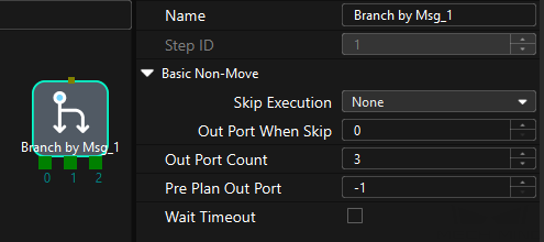
mm_set_branch: The number of the exit port of the Branch by Msg Step to take. When the next Step is a “Branch by Msg” Step, the Mech-Viz project will wait for this command to specify the exit port to take.
Calling Sequence
This instruction must be called after the startViz instruction.
Input Parameters
- Branch ID
-
This parameter specifies the “Branch by Msg” Step by its ID. Valid values: positive integers. The Step ID is displayed in the Step parameter panel. For example, the Step ID of the Step in the image above is 1.
- Branch Port
-
This parameter indicate the exit port of the Branch by Msg Step. Valid values: positive integers. When the parameter value is set to N, the Mech-Viz project exits from the port with an ID of N-1 of the Branch by Msg Step.
mm_set_index (set current index in Mech-Viz)
Description
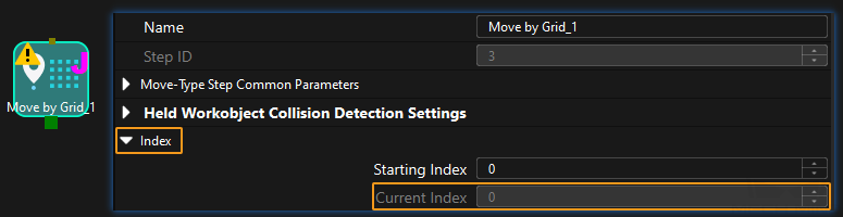
Select mm_set_index to set the current index value for Mech-Viz indexing steps. Index-type Steps are Steps that include the Index section, which include Move by Grid, Move by List, Custom Pallet Pattern, and Predefined Pallet Pattern.
Calling Sequence
Typically, a “Message Branch” step precedes an indexing steps.The robot controller shall first call the startViz instruction, followed by the addFunc instruction with the mm_set_index parameter selected, and finally the addFunc instruction with the mm_set_branch parameter selected. This is to ensure that Mech-Viz has enough time to set the Current Index value.
Input Parameters
- Skill Num
-
This parameter specifies the Step ID of the Index-type Step. Valid values: positive integers. The Step ID is displayed in the Step parameter panel. For example, the Step ID of the Step in the image above is 3.
- Index Num
-
This parameter sets the value of the Current Index parameter of index-type Steps. Valid values: positive integers. When this parameter value is set to N, the current index of the corresponding Step is N-1.
mm_set_model (to switch the Mech-Vision parameter recipe)
Description
The Mech-Visionmm_set_modelMech-Vision command to switch the Mech-Vision parameter recipe The image below shows how to manually switch the parameter recipe for a Mech-Vision project. For details about parameter recipes, see the parameter recipe guide.
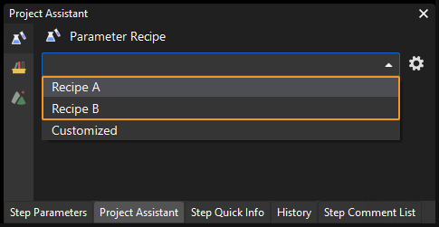
Calling Sequence
This instruction must be called before the startVis instruction.
Input Parameters
- Project ID
-
Mech-Vision project ID. You can view the project ID of a Mech-Vision project in the Project List section of Mech-Vision. The project ID is the number before the project name.
- Model ID
-
This parameter indicates the parameter recipe ID in the Mech-Vision project. For details on how to check the parameter recipe ID, see View the Parameter Recipe ID.
mm_set_boxsize (input object dimensions to Mech-Vision project)
Description
The Mech-Visionmm_set_boxsizeMech-Vision command sends the object dimensions to the Mech-Vision project. The object dimensions are the values of the Box Size Settings parameters in the Read Object Dimensions Step.
| When you use this command, only one Read Object Dimensions Step is allowed in the Mech-Vision project. Otherwise, the vision system will return an error. |
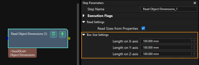
Calling Sequence
This instruction must be called before the startVis instruction.
Input Parameters
- Project ID
-
Mech-Vision project ID. You can view the project ID of a Mech-Vision project in the Project List section of Mech-Vision. The project ID is the number before the project name.
- Length, Width, Height
-
The preceding three parameters sequentially input the length, width, and height of the object to the Mech-Vision project. The length, width, and height are measured in millimeters (mm). These values are read by the Read Object Dimensions Step and set for the parameters Length on X-axis, Length on Y-axis and Length on Z-axis.
mm_set_property (set Mech-Viz step parameter)
Description
The Mech-Visionmm_set_propertyMech-Vision command sets the step parameter for the Mech-Vision project.
Calling Sequence
This instruction must be called before the startViz instruction.
Input Parameters
- ID
-
This parameter corresponds to the Config ID field defined in the property_config file.
From the toolbar of Mech-Vision, go to . Click Property Configuration to open the property_config file.
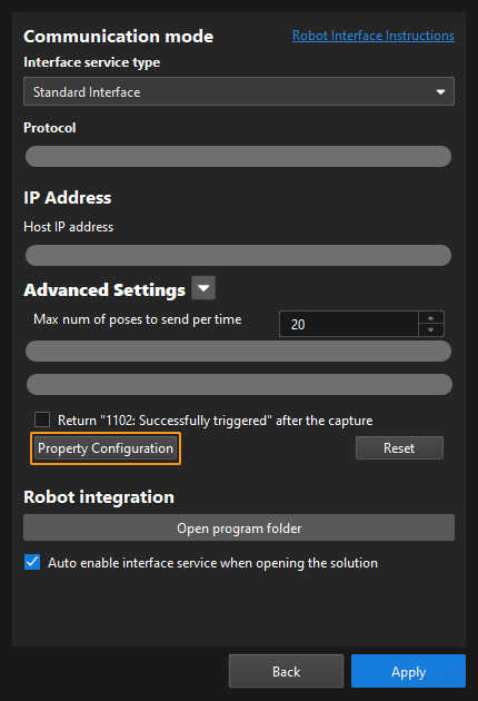
Before sending this command, you should define a Config ID and its corresponding Step ID, parameter key name and parameter value in the following format in the property_config file.
write, Config ID, Step ID, parameter key name, parameter value
write
Indicates that this line is used to set the parameter value of a Step.
Config ID
Specifies an ID, which is a positive integer and can be used repeatedly.
Step ID
Specifies the Step whose parameter value the robot requires to read.
parameter key name
Specifies the key name of the parameter whose value the robot requires to set.
parameter value
Specifies the value that the robot sets for the parameter.
-
The property_config file can contain more than one “write” command, and these commands can use a Config ID repeatedly. That is, one Config ID can be used to set values for multiple parameters.
-
You can check the parameter key name in the Key Query Tool. In Mech-Viz, click File in the menu bar. In the lower-left corner, click Options. Click Developer mode, click OK, and then restart the software. In the menu bar of the software, select to open the tool. Click a Step icon, and all key names of the Step will be displayed in the middle column. Each key name corresponds to a Step parameter name displayed in the parameter panel. You can also click a key name and check its corresponding parameter name in the “Details” panel.
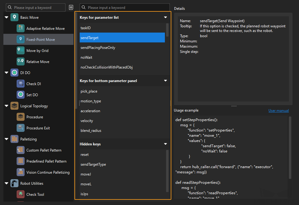
-
In the property_config file, lines starting with “#” are comments, which will not be executed by the program.
-
Remember to save the file after editing, and then restart the interface service on the toolbar of Mech-Vision.
-
Output Parameters
- g_mm_status
-
This parameter indicates the name of the variable for storing the command execution status code. Status code 2108 is returned for a successful command execution. If a command fails to be run, a specific error code is returned. For details, see Status Codes and Troubleshooting.
mm_get_property (get Mech-Viz step parameter)
Description
The mm_get_property command gets the step parameter in the Mech-Viz project.
Calling Sequence
This instruction must be called before the startViz instruction.
Input Parameters
- ID
-
This parameter corresponds to the Config ID field defined in the property_config file.
From the toolbar of Mech-Vision, go to . Click Property Configuration to open the property_config file.
Before calling this function, you should define a Config ID and its corresponding Step ID and parameter key name in the following format in the property_config file.
read, Config ID, Step ID, parameter key name
read
Indicates that this line is used to read the parameter value of a Step.
Config ID
Specifies a unique ID, which is a positive integer. One Config ID corresponds to only one parameter value of a Step. To read multiple parameter values, you should set different Config IDs.
Step ID
The Step ID of the Step whose parameter is to be read.
parameter key name
Specifies the key name of the parameter whose value the robot requires to read.
-
You can check the parameter key name in the Key Query Tool. In Mech-Viz, click File in the menu bar. In the lower-left corner, click Options. Click Developer mode, click OK, and then restart the software. In the menu bar of the software, select to open the tool. Click a Step icon, and all key names of the Step will be displayed in the middle column. Each key name corresponds to a Step parameter name displayed in the parameter panel. You can also click a key name and check its corresponding parameter name in the “Details” panel.
-
In the property_config file, lines starting with “#” are comments, which will not be executed by the program.
-
Remember to save the file after editing, and then restart the interface service on the toolbar of Mech-Vision.
The property_config file can have multiple read commands. The Config ID in these commands must be different.
-
Output Parameters
- dataValue
-
This parameter stores the parameter value of the Step.
- g_mm_status
-
This parameter indicates the name of the variable for storing the command execution status code. Status code 2109 is returned for a successful command execution. If a command fails to be run, a specific error code is returned. For details, see Status Codes and Troubleshooting.
mm_get_notify (get message from notify step)
Description
The mm_get_notify command get message from notify step. When the Mech-Vision project or Mech-Viz project is executing the Notify Step, the vision system returns the message predefined in the Notify Step.
Before sending this command, complete the following settings for the Notify Step.
-
For a Notify Step in the Mech-Vision project:
-
Connect the Notify Step to the right side of another Step. The Output Step is used in the example in the image below.

-
Select Trigger Control Flow Given Output in the parameter panel of the Output Step.
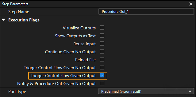
-
In the parameter panel of the Notify Step, enter Standard Interface Notify (the value cannot be modified) for Service Name. Enter a positive integer for Message, for example, 1001.
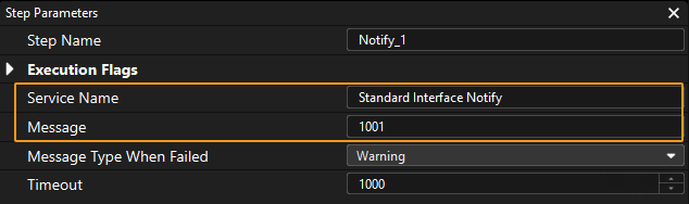
-
-
For a Notify Step in the Mech-Viz project:
-
Connect the Notify Step to a proper Step in the workflow.
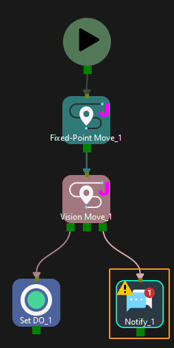
-
In the parameter panel of the Notify Step, select Standard Interface. Enter a positive integer for Message, for example, 1000.
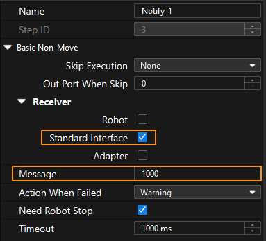
-
Calling Sequence
Output Parameters
- dataValue
-
This parameter stores the message from the Notify Step. Only positive integer messages are supported at the moment.
mm_get_dolist (obtains the gripper DO list)
Description
The mm_get_dolist command obtains the planned control signals of multi-section vacuum gripper from Mech-Vision or Mech-Viz project.
Before using this command, you must perform the following configurations in Mech-Vision or Mech-Viz.
-
Configure the Mech-Vision project
-
In the Path Planning Step, click Config wizard. In Global configuration, enable Box depalletizing.
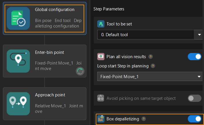
-
In the Path Planning Step, click Config wizard, and then double-click the name of the robot tool. In the pop-up window, select Depalletizing vacuum gripper for Tool type, click Configure depalletizing vacuum gripper, and then configure DO signals according to needs.
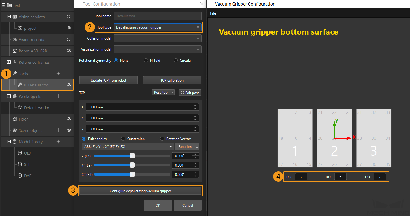
-
-
Configure the Mech-Viz project
-
In the Vision Move Step of Mech-Viz, set Select Picking Method to Box depalletizing.

-
In Mech-Viz, double-click the tool name, select Depalletizing vacuum gripper for Tool type, click Configure depalletizing vacuum gripper, and then configure the DO signals according to needs.
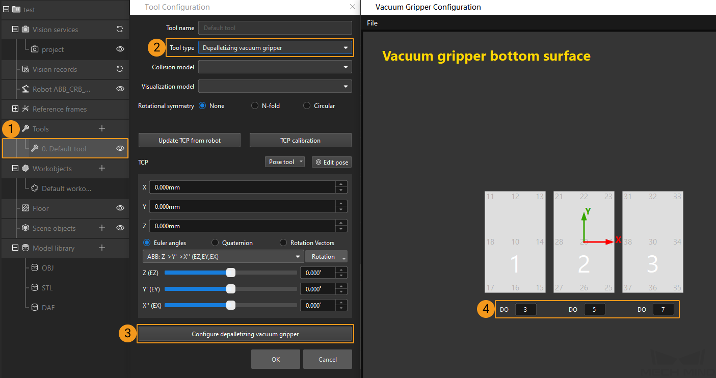
-
Calling Sequence
This command must be called after the getData command. This means that the robot must obtain the motion path and then obtain gripper DO signals of the Vision Move waypoint.
Input Parameters
- Project ID
-
This parameter specifies the source of the DO signal list. Valid values: 0 to the largest positive integer.
-
0: Get DO signal list from Mech-Viz.
-
A positive integer: Get DO signal list from Mech-Vision. The positive integer is the Mech-Vision project ID.
-
- Block Num
-
This parameter specifies the number of gripper sections that are specified in the gripper configuration tool. For example, the number of gripper sections in the above image is 3.
Output Parameters
- Do List
-
This parameter specifies a variable name. This variable will store the acquired DO signal. The DO signals returned vary based on the deployed project.
-
Gripper DO signals planned by the Mech-Vision project
-
Under Global Configuration of the path planning tool, if Plan all vision results is disabled, this command returns 64 gripper DO signals that are planned in this round. Valid DO signals are non-negative integers ranging from 0 to 999. Invalid DO signals are -1, which serves as a placeholder.
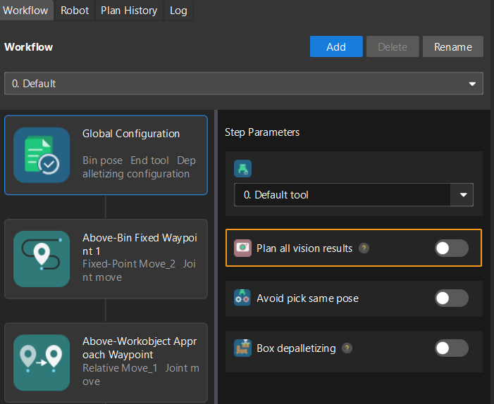
For example, valid DO signals in the table below are 1, 3, 5, and 6, which means that the robot will set the values of these DO signals to ON.
1st
2nd
3rd
4th
5th
6th
7th
8th
…
63rd
64th
1
3
5
6
−1
−1
−1
−1
…
−1
-1
-
Under Global Configuration of the path planning tool, if Plan all vision results is enabled, Mech-Vision can perform multiple rounds of planning based on the same vision result. The 64 gripper DO signals returned by this command are obtained during all rounds of planning. In this case, you can use the number of vacuum gripper sections to differentiate the gripper DO signals obtained during each round of planning.
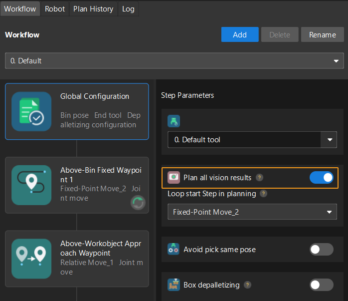
For example, if the number of vacuum gripper sections is 4 and the command returns 64 DO signals in total, each 4 DO signals are multi-section vacuum gripper signals obtained during each round of planning.
First round of planning
Second round of planning
…
16th round of planning
1st
2nd
3rd
4th
5th
6th
7th
8th
…
61st
62nd
63rd
64th
1
3
4
-1
1
4
-1
-1
…
-1
-1
-1
-1
-
-
Gripper DO signals planned by the Mech-Viz project
-
If Reuse Vision Result is not selected for the Vision Move Step, this command returns 64 gripper DO signals that are planned during this round. Valid DO signals are non-negative integers ranging from 0 to 999. Invalid DO signals are -1, which serves as a placeholder.
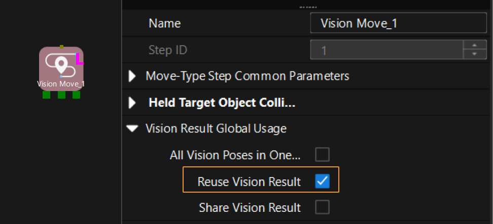
For example, valid DO signals in the table below are 1, 3, 5, and 6, which means that the robot will set the values of these DO signals to ON.
1st
2nd
3rd
4th
5th
6th
7th
8th
…
63rd
64th
1
3
5
6
-1
-1
-1
-1
…
-1
-1
-
If Reuse Vision Result is selected for the Vision Move Step and the Vision Move Step is used in a loop, Mech-Viz can perform multiple rounds of planning based on the same vision result. The 64 gripper DO signals returned by this command are obtained during all rounds of planning. In this case, you can use the number of vacuum gripper sections to differentiate the gripper DO signals obtained during each round of planning.
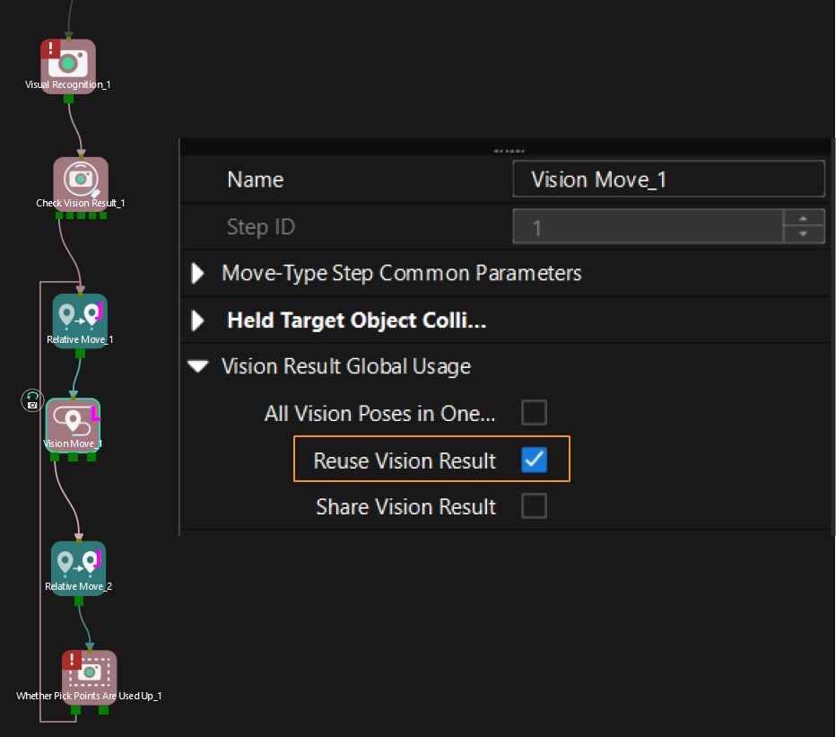
For example, if the number of vacuum gripper sections is 4 and the command returns 64 DO signals in total, each 4 DO signals are multi-section vacuum gripper signals obtained during each round of planning.
First round of planning
Second round of planning
…
16th round of planning
1st
2nd
3rd
4th
5th
6th
7th
8th
…
61st
62nd
63rd
64th
1
3
4
-1
1
4
-1
-1
…
-1
-1
-1
-1
-
-
Calibration
Description
This command is used for robot hand-eye calibration (extrinsic parameter calibration). This command must be used together with the Camera Calibration setting to complete automatic calibration. You can find Camera Calibration in the toolbar of Mech-Vision. For more information, see AUBO (ARCS) Automatic Calibration.