Communication Configuration and Example Program Usage
This topic provides instructions on setting up the Standard Interface communication based on the MC protocol between a KEYENCE PLC (with Built-in Ethernet Port) and the Mech-Mind Vision System.
Hardware and Software Requirements
|
The models and versions listed below are tested and can be used. For other models and versions, you may refer to this guide for operation. If any issues occur, please contact Mech-Mind Technical Support. |
Hardware
-
KEYENCE PLC with a built-in Ethernet port
In this example, the KV-8000 CPU model is used.
-
Power adapter: 220V AC to 24V DC
-
An IPC and a computer
-
USB Type A Male to Type B Male cable (used to download PLC programs)
-
Ethernet cable (used to connect the IPC and the PLC)
Software
| Software | Description | Installed Location |
|---|---|---|
KV STUDIO 11.62 |
KEYENCE PLC programming software |
Computer that is used for KEYENCE PLC programming |
Mech-Vision and Mech-Viz |
Mech-Mind Vision System |
IPC |
In addition to the above software, please copy the example program files (used to implement the features of various interface commands) to a computer that has with KV STUDIO installed. The example program files are stored in the folder where Mech-Vision and Mech-Viz are installed: Communication Component/Robot_Interface/Mitsubishi MC/Keyence.
| The firewall on the IPC or computer must be turned off. |
Create and Configure the PLC Project
Create a PLC Project
-
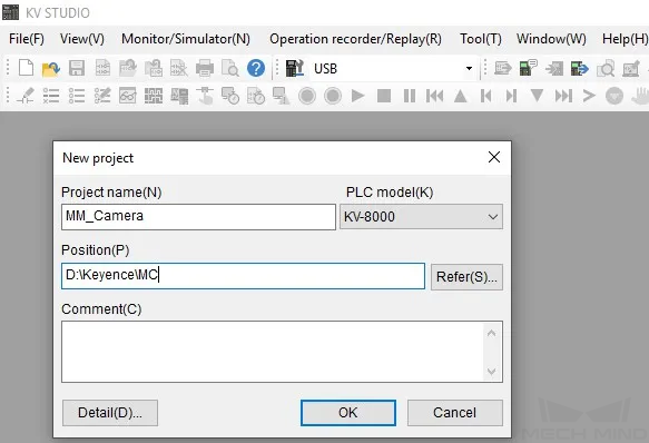
Open the KV STUDIO software and click New project in the toolbar. In the New project dialog box, enter the project name, select KV-8000 for PLC model, click Refer to select the project path, and then click OK.
-
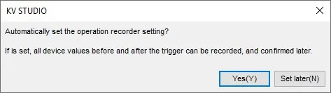
In the following dialog box, click Yes.
-
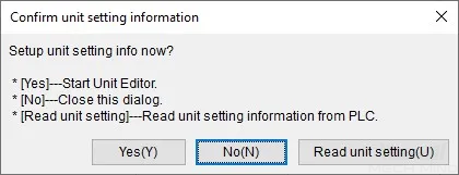
In the following dialog box, click No.
Configure Communication Parameters of MC Protocol
-
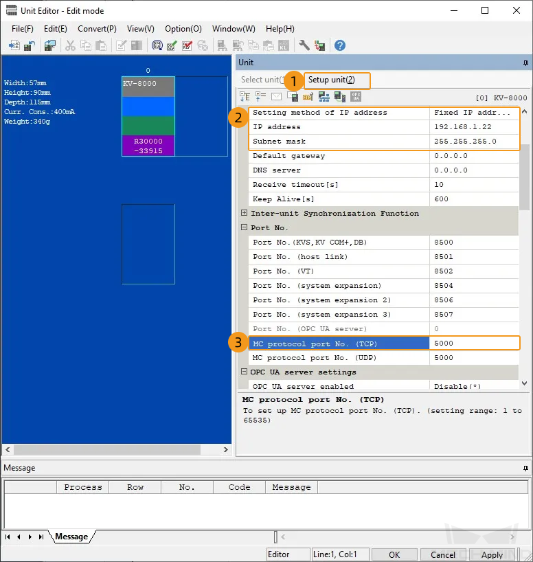
In the Project section, expand Unit configuration and then double-click KV-8000.
-
In the Unit section, click Setup unit, set IP address for the PLC (such as 192.168.1.22), set MC protocol port No. (TCP) to 5000, and then click OK.
Import Example Programs
| Before you add an example program to a project already in use, it is recommended to import it to a new project and test it first. |
-
In the menu bar of KV STUDIO, select . The Import program dialog box will appear.

-
In the Import program dialog box, open the program folder copied from the IPC, select all files in the folder, and then click Open.
The example program files are stored in the folder where Mech-Vision and Mech-Viz are installed: Communication Component/Robot_Interface/Mitsubishi MC/Keyence. You need to copy the Keyence folder from the IPC to the computer that has KV STUDIO installed in advance.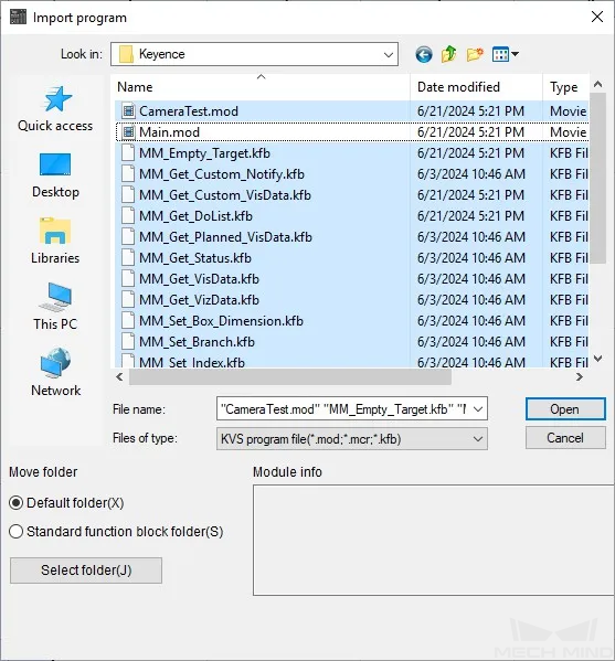
-
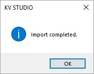
In the following dialog box, click OK.
Download Communication Configuration and Example Programs to PLC
-
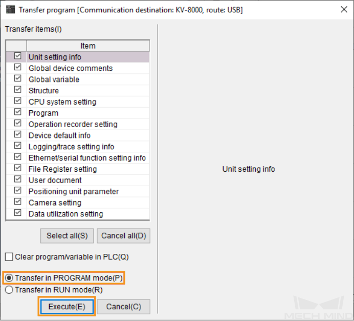
In the menu bar of KV STUDIO, click the Transfer to PLC→Monitor mode icon. The Transfer program dialog box will appear.

-
In the following dialog box, keep the default settings and then click Execute.
-
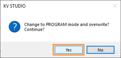
During the transfer, the following dialog box will appear. Click Yes to change the PLC to the overwrite mode.
-
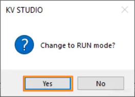
After the transfer is complete, the following dialog box will appear. Click Yes to change the PLC to the run mode.
Set up Robot Communication Configuration
-
Click Robot Communication Configuration on the toolbar of Mech-Vision.
-
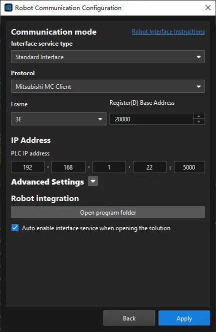
In the Robot Communication Configuration dialog box, complete the following configurations.
-
Click the Select robot drop-down menu, and select Listed robot. Click Select robot model, and select the robot model that you use. Then, click Next.
-
In the Communication mode section, select Standard Interface for Interface service type, Mitsubishi MC Client for Protocol, and 3E for Frame. You can set Register(D) Base Address according to actual needs. The value is set to 20000 in this example. In addition, the MM_Interface structure occupies 1528 D Registers in total.
The start address of Register (D) must be consistent with the start address of the MM_Interface structure variable (MM_Camera). If they are inconsistent, please modify them according to actual needs.
-
In the PLC IP address field, enter the IP address and port number of the specific PLC in use.
-
(Optional) Select Auto enable interface service when opening the solution.
-
Click Apply.
-
-
On the main interface of Mech-Vision, make sure that the Robot Communication Configuration switch on the toolbar is flipped and has turned blue.

Check Communication
-
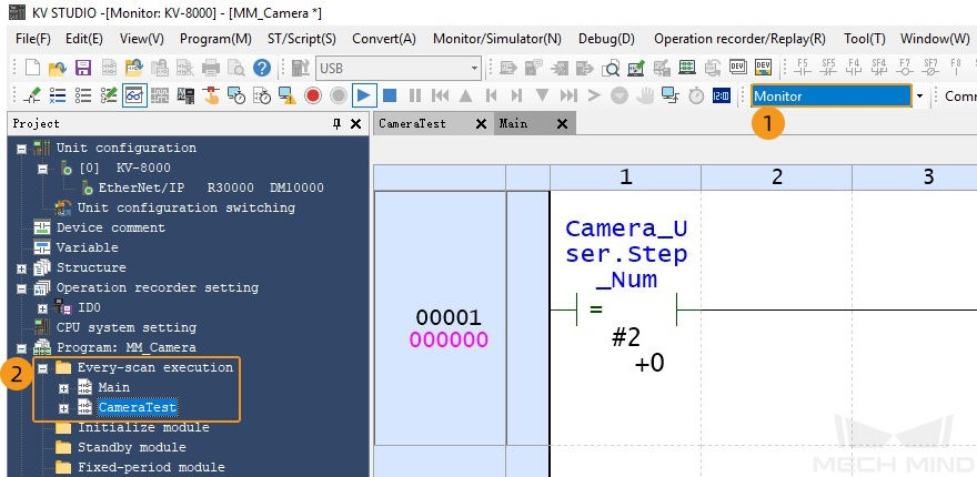
In Monitor mode of KV STUDIO, expand items in the Project section to find CameraTest in Every-scan execution and then double-click CameraTest.
-
In the toolbar, click the registration monitor icon to open the Registration monitor dialog box, and then add MM_Camera in the dialog box.
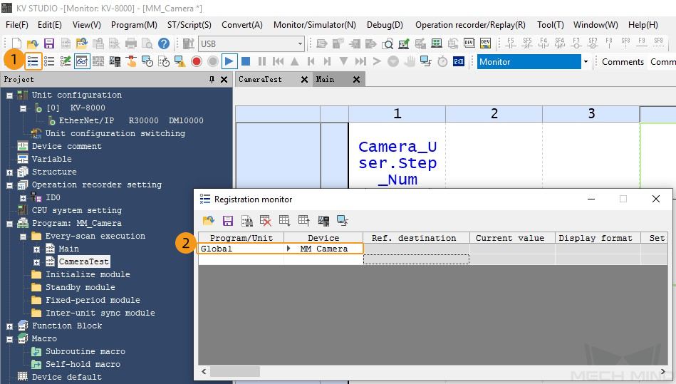
-
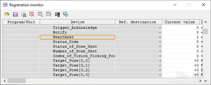
In the Registration monitor dialog box, expand MM_Camera to find Heartbeat. If the connection is established successfully, the current value of Heartbeat will keep changing.
-
The PLC is successfully connected if the following message is displayed in the Console tab of Mech-Vision Log panel: Connect to Melsec PLC successfully.
If you don’t see this log message, please check if:
-
The hardware network connection is normal.
-
The Robot Communication Configuration option on the toolbar of Mech-Vision is enabled.
-
The PLC program is downloaded to the PLC.
-
Test with Mech-Vision/Mech-Viz Project
This section introduces how to use the example program FB to trigger the Mech-Vision project to run and obtain the vision result and trigger the Mech-Viz project to run and obtain the planned path.
Prerequisites
-
Return to Mech-Vision and create a Mech-Vision project. In the Project List section of Mech-Vision, right-click the solution and select Autoload Solution. Projects in the solution are also autoloaded. Meanwhile, the project ID will show up before each project name.
-
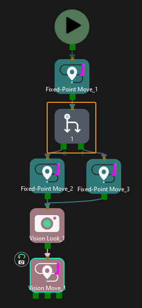
Create a Mech-Viz project. Right-click the project name in the project resource panel in Mech-Viz and select Autoload Project. The Mech-Viz project used for testing should contain a “Branch by Msg” Step that has been renamed to 1 as shown below.
Get Vision Result from Mech-Vision
Configure Programs
In the CameraTest program dialog box, complete the following configurations.
-
Set the value of Vision_Proj_Num to 1. Then, project No.1 in Mech-Vision will be started.
-
Set the value of Req_Pose_Num to 0. Then, Mech-Vision will return all vision points.
-
Set the value of Robot_Pose_Type to 0. Then, the image-capturing pose does not need to be sent to the Mech-Vision project. For example, the image-capturing pose does not need to be sent when the camera is mounted in eye-to-hand mode.
Run the Mech-Vision Project
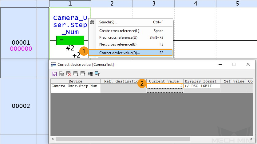
-
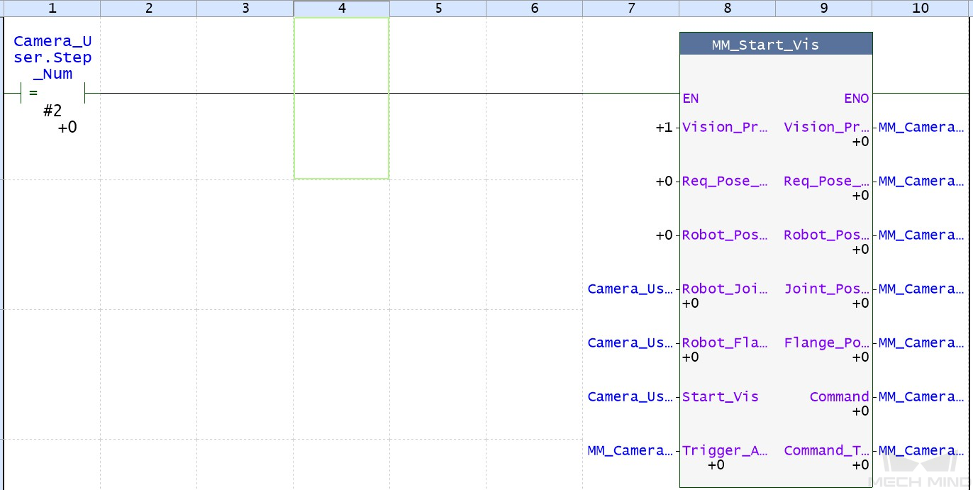
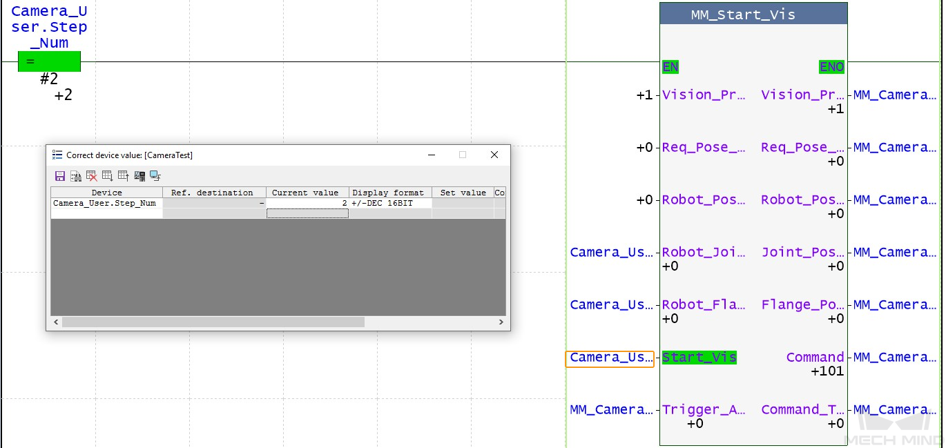
Right-click Camera_User.Step_Num to change its value. In the dialog box that appears, change the current value of Camera_User.Step_Num to 2 to enable MM_Start_Vis.
-
Double-click the input variable CameraUser.Start_Vision of MM_Start_Vis to set CameraUser.Start_Vision to 1 to trigger the Mech-Vision project to run. Then, double-click CameraUser.Start_Vision to reset CameraUser.Start_Vision to 0.
-
In the Registration monitor dialog box, if the Mech-Vision project has been successfully triggered, 1102 is displayed for Status_Code.
If 10XX is displayed for Status_Code and you want to troubleshoot the issue, see Status Codes and Troubleshooting. 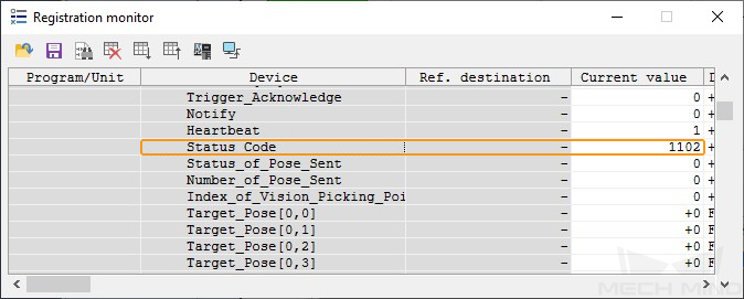
Get Vision Result from Mech-Vision
-
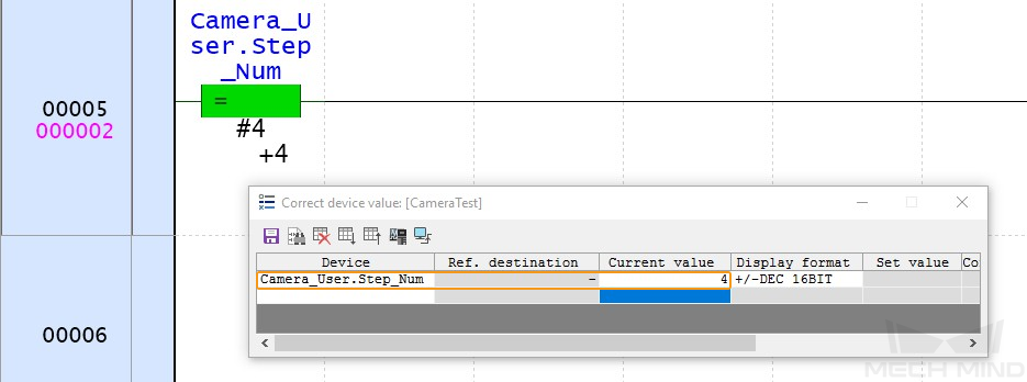
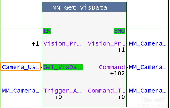
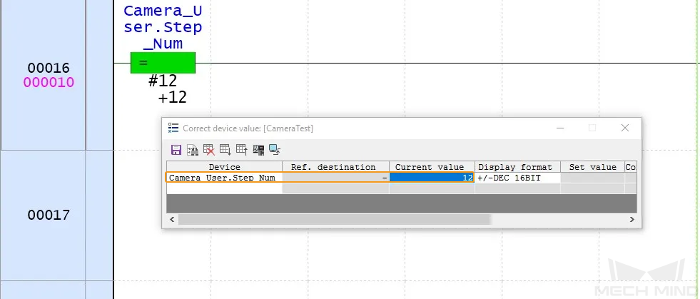
In the Correct device value dialog box, change the current value of Camera_User.Step_Num to 4 to enable MM_Get_VisData.
-
Double-click the input variable CameraUser.Get_VisData of MM_Get_VisData to set CameraUser.Get_VisData to 1 to obtain the vison result. Then, double-click CameraUser.Get_VisData to reset CameraUser.Get_VisData to 0.
-
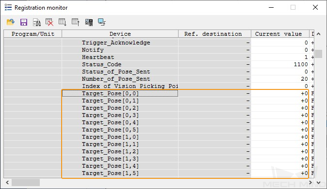
In the Registration monitor dialog box, if the vison result has been successfully obtained, 1100 is displayed for Status_Code. Check the values of Target_Pose. The values indicate the pose data of vision points.
If 10XX is displayed for Status_Code and you want to troubleshoot the issue, see Status Codes and Troubleshooting. 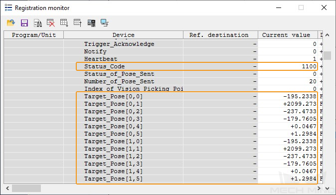
Obtain Planned Path from Mech-Viz
Configure Programs
-
In the Correct device value dialog box, change the current value of Camera_User.Step_Num to 12 to enable MM_Empty_Target.
-
Double-click the input variable CameraUser.Start_Empty of MM_Empty_Target to set CameraUser.Start_Empty to 1 to clear the obtained vision result. Then, double-click CameraUser.Start_Vision to reset CameraUser.Start_Vision to 0.
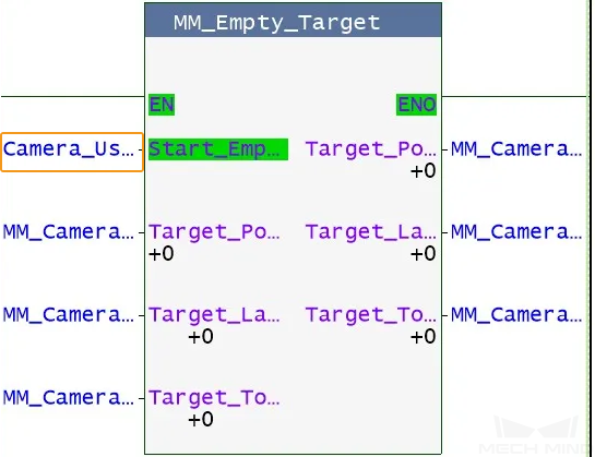
In the Registration monitor dialog box, all values of Target_Pose are 0.
-
Set the values of Branch_Name and Branch_Exit_Port both to 1 to indicate that the project takes port No.1 of the Branch by Msg No.1 Step of the Mech-Viz project.
-
Set the value of Request_Pose_Type to 1 to indicate that the waypoints planned by Mech-Viz will be returned in joint positions.
Run Mech-Viz Project
-
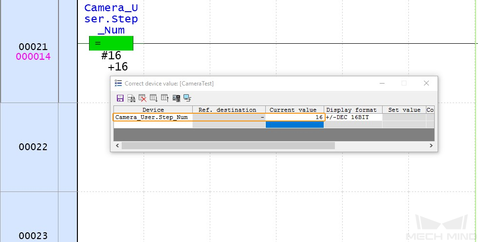
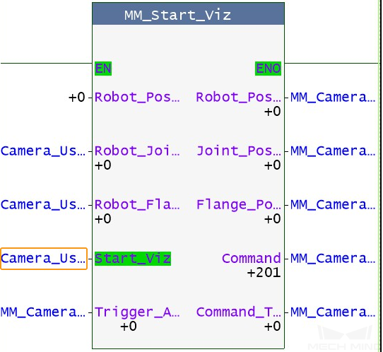
In the Correct device value dialog box, change the current value of Camera_User.Step_Num to 16 to enable MM_Start_Viz.
-
Double-click the input variable CameraUser.Start_Viz of MM_Start_Viz to set CameraUser.Start_Viz to 1 to trigger the Mech-Viz project to run. Then, double-click CameraUser.Start_Viz to reset CameraUser.Start_Viz to 0.
-
In the Registration monitor dialog box, if the Mech-Viz project has been successfully triggered, 2103 is displayed for Status_Code.
If 20XX is displayed for Status_Code and you want to troubleshoot the issue, see Status Codes and Troubleshooting. 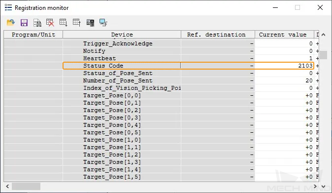
Set the Exit Port for the Branch by Msg Step in Mech-Viz
-
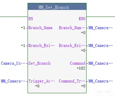
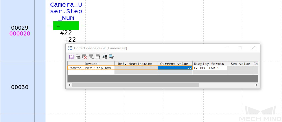
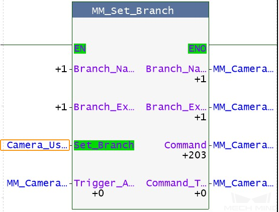
In the Correct device value dialog box, change the current value of Camera_User.Step_Num to 22 to enable MM_Set_Branch.
-
Double-click the input variable CameraUser.Set_Branch of MM_Set_Branch to set CameraUser.Set_Branch to 1 to set the exit port of the Branch by Msg Step in the Mech-Viz project. Then, double-click CameraUser.Set_Branch to reset CameraUser.Set_Branch to 0.
-
In the Registration monitor dialog box, if the exit port has been successfully set for the Branch by Msg Step in Mech-Viz, 2105 is displayed for Status_Code.
If 20XX is displayed for Status_Code and you want to troubleshoot the issue, see Status Codes and Troubleshooting. 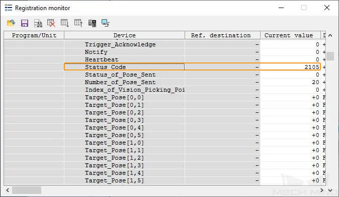
Get Planned Path in Mech-Viz
-
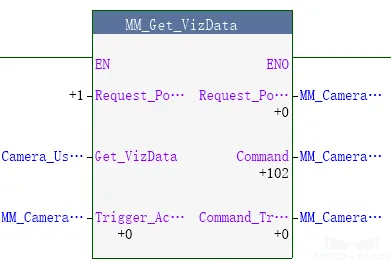
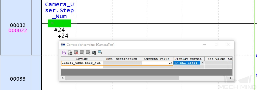
In the Correct device value dialog box, change the current value of Camera_User.Step_Num to 24 to enable MM_Get_VizData.
-
Double-click the input variable CameraUser.Get_VizData of MM_Get_VizData to set CameraUser.Get_VizData to 1 to obtain the planned path from Mech-Viz. Then, double-click CameraUser.Get_VizData to reset CameraUser.Get_VizData to 0.
-
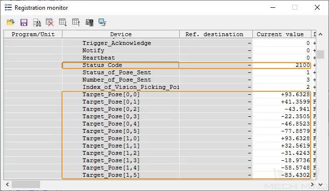
In the Registration monitor dialog box, if the planned path has been successfully obtained, 2100 is displayed for Status_Code. Check the values of Target_Pose. The values indicate the pose data of waypoints.
If 20XX is displayed for Status_Code and you want to troubleshoot the issue, see Status Codes and Troubleshooting.