Initialize the parameters |
-
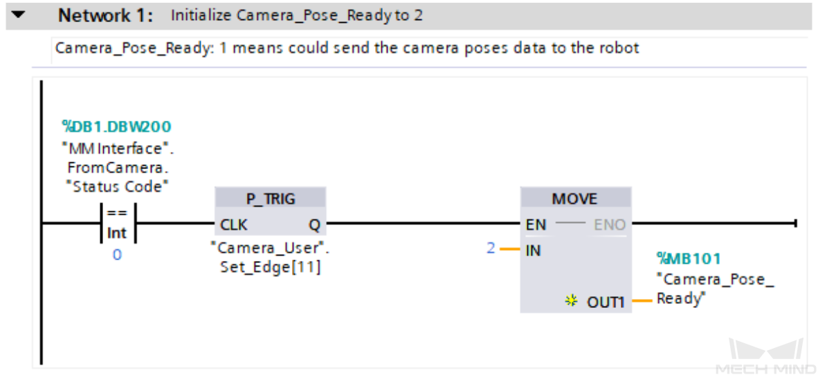
"MM Interface".FromCamera."Status Code": A vision system status code.
-
P_TRIG: Detect the signal rising edge for the logical operation result ("MM Interface".FromCamera."Status Code" equals 0).
-
MOVE: Set "Camera_Pose_Ready" to 2.
-
"Camera_Pose_Ready": Indicate whether the PLC obtained the vision result. Valid values:
-
0: The PLC did not obtain the vision result when the camera was about to capture images or had already captured images, or when Mech-Vision was calculating the vision result.
-
1: The camera captured images, and the PLC obtained the vision result.
-
2: The camera was ready to start capturing images for the first time, and the PLC did not obtain the vision result.
As such, Network 1 indicates that only when "MM Interface".FromCamera."Status Code" equals 0 and P_TRIG detects a rising edge, "Camera_Pose_Ready" is initialized to 2.
|
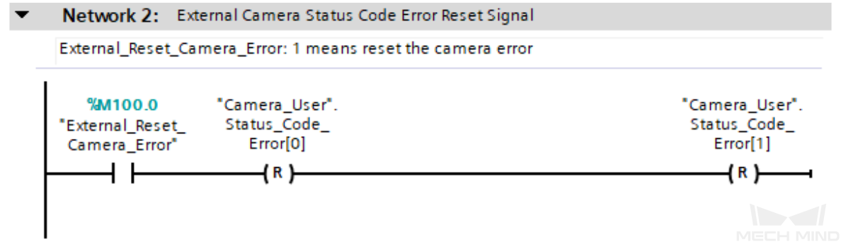
Reset vision system status code exception flags |
-
"Camera_User".Status_Code_Error[0]: A vision system status code exception flag. True indicates that the Mech-Vision project was not successfully run, i.e., an exception occurred in the vision system.
-
"Camera_User".Status_Code_Error[1]: A vision system status code exception flag. True indicates that the Mech-Vision project failed to output the vision result, i.e., an exception occurred in the vision system.
-
"External_Reset_Camera_Error": An external reset signal. When an exception occurs in the vision system and the signal changes from False to True, reset the succeeding "Camera_User".Status_Code_Error[0] and "Camera_User".Status_Code_Error[1].
As such, Network 2 resets "Camera_User".Status_Code_Error[0] and "Camera_User".Status_Code_Error[1] and sets "Camera_User".Step_Num to 0 when "External_Reset_Camera_Error" is active.
|
Set interface parameters for the Mech-Vision project |
-
"User_Vision_Project_Num": The Mech-Vision project ID.
-
"User_Robot_Pose_Type": Specify the pose type of the real robot to input to the Mech-Vision project. This value of this parameter should be set as the value of Robot_Pose_Type of the MM_Start_Vis command. In this example, the parameter value is 0. You can modify the value as needed.
-
"Camera_User".Robot_Pose[0,0] ~ [0,5]: Six pieces of joint position data of the robot. This value of this parameter should be set as the value of Robot_Pose[0,0]~[0,5] of the MM_Start_Vis command. In this example, the parameter value is 0.0. You can modify the value as needed and add the robot flange pose data, i.e., the value of the Robot_Pose[1,0]~[1,5] parameter in the MM_Start_Vis command.
As such, in Network 3, Mech-Vision project ID is set to 1 and "User_Robot_Pose_Type" is set to 0. If the Mech-Vision project ID is set to 1 and "User_Robot_Pose_Type" is set to 0, "Camera_User".Robot_Pose[0,0]~[0,5] are set to 0.0 sequentially.
|
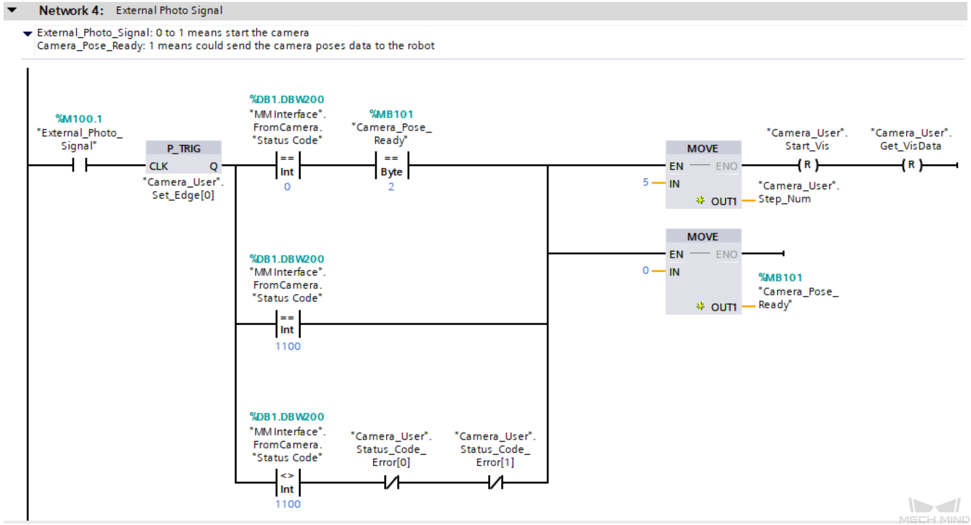
Trigger external image capturing |
-
"External_Photo_Signal": The external signal to trigger image capturing when a rising edge occurs.
-
"MM Interface".FromCamera."Status Code": A vision system status code. 1102 indicates that the PLC successfully triggered the Mech-Vision project to run. 1100 indicates that the PLC successfully obtained the vision result.
-
"Camera_User".Start_Vis: The flag that triggers the Mech-Vision project to run when the rising edge occurs.
-
"Camera_User".Get_VisData: The flag that triggers the retrieval of Mech-Vision vision result when the rising edge occurs.
As such, Network 4 indicates that the external signal to trigger image capturing when a rising edge occurs is retrieved, and then the following three image capturing operations are performed.
-
An image is captured for the first time. "MM Interface".FromCamera."Status Code" is set to 0, and "Camera_Pose_Ready" is set to 2.
-
An image is captured normally at the next time. "MM Interface".FromCamera."Status Code" equals 1100.
-
An error is reported when an image is captured at the next time. "MM Interface".FromCamera."Status Code" does not equal 1100, and both "Camera_User".Status_Code_Error[0] and "Camera_User".Status_Code_Error[1] are set to False.
Finally, "Camera_User".Step_Num is set to 5, "Camera_Pose_Ready" is set to 0, and "Camera_User".Start_Vis and "Camera_User".Get_VisData are reset.
|
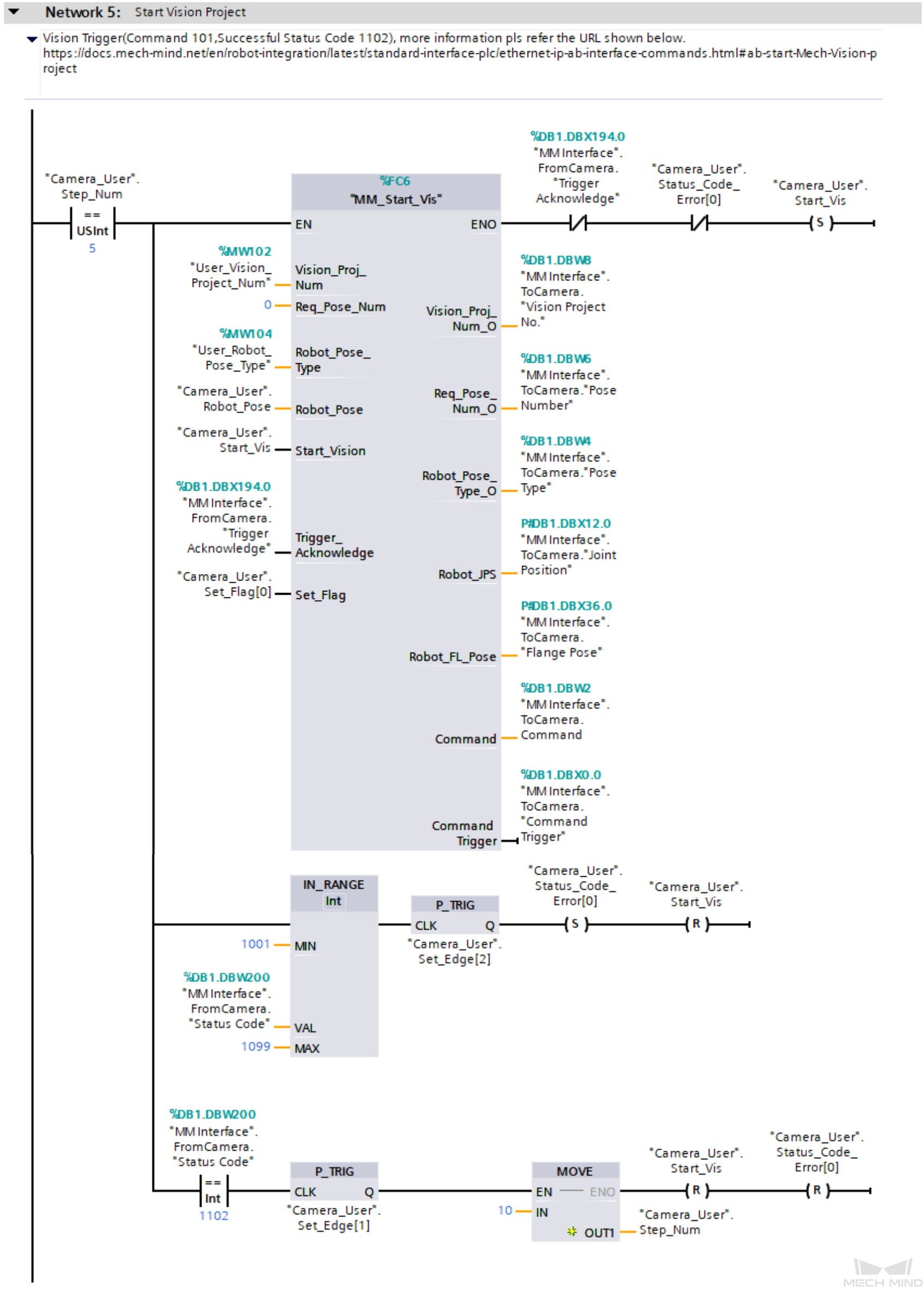
Trigger the Mech-Vision project to run and determine whether the project is triggered successfully for different processing |
|
|
For more information about input and output parameters in MM_Start_Vis, see MM_Start_Vis.
|
Network 5 indicates that if "Camera_User".Step_Num is set to 5, the following operations are performed.
-
MM_Start_Vis is enabled. In this case, Req_Pose_Num is set to 0 by default, which means all vision points are obtained. The maximum number of vision points is 20.
-
When "MM Interface".FromCamera."Trigger Acknowledge" is set to False and "Camera_User".Status_Code_Error[0] is set to False, "Camera_User".Start_Vis is set and the PLC triggers the Mech-Vision project to run.
-
If "MM Interface".FromCamera."Status Code" is between 1001 and 1099 (inclusive), it indicates a vision system error. At this point, the rising edge of this logical output is captured using the P_TRIG command. When "MM Interface".FromCamera."Trigger Acknowledge" is True, "Camera_User".Status_Code_Error[0] is set, and "Camera_User".Start_Vis is reset. For information about the cause of a specific status code, see Standard Interface status codes and error codes.
-
If the value of "MM Interface".FromCamera."Status Code" is 1102, the vision system has successfully executed the command sent by the PLC. In this case, the P_TRIG command is called to retrieve the rising edge for the logical output, a value of 10 is assigned to "Camera_User".Step_Num, and "Camera_User".Start_Vis and "Camera_User".Status_Code_Error[0] are reset.
|
Obtain the vision result of the Mech-Vision project and determine whether the vision result is obtained successfully for different processing |
|
|
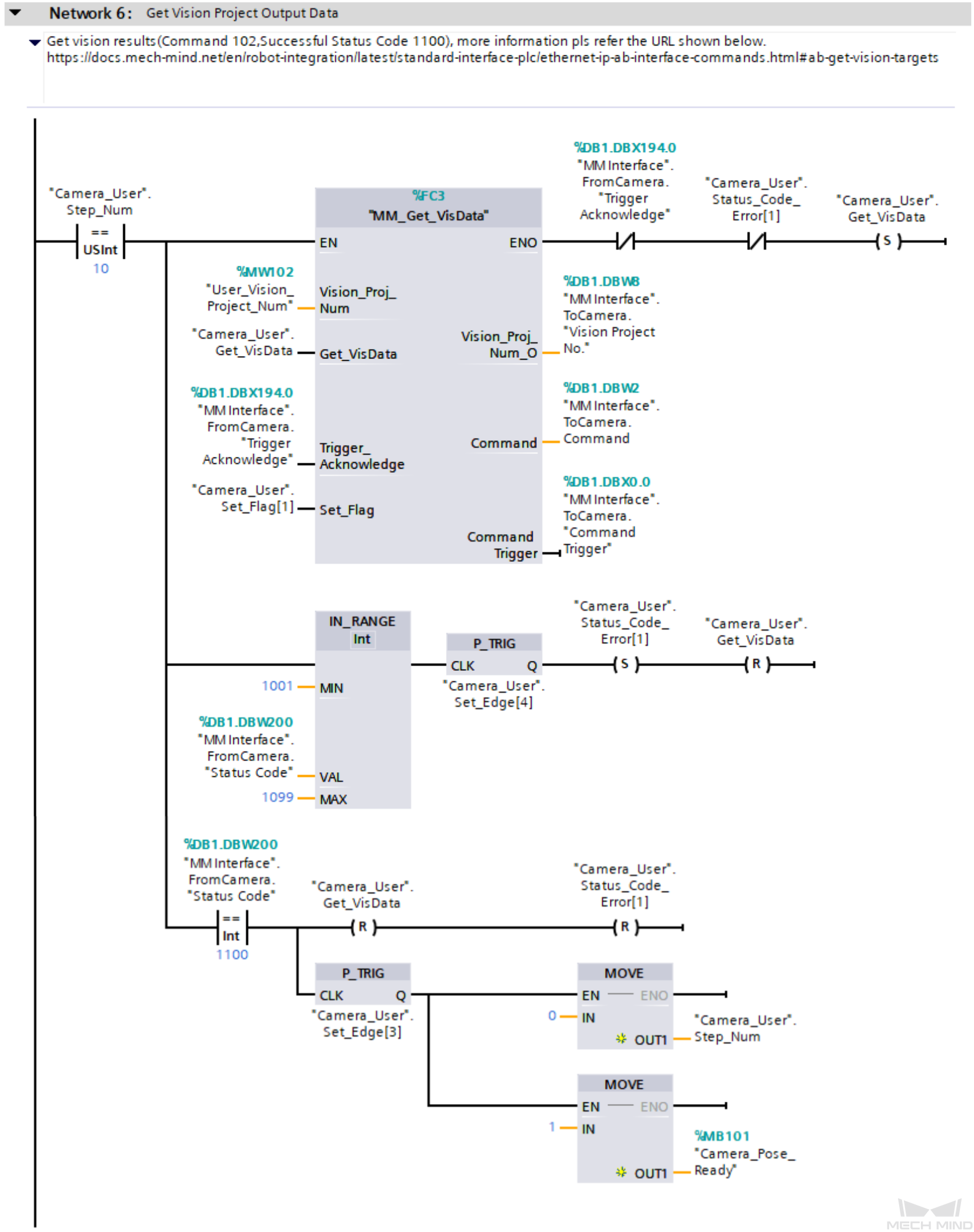
For more information about input and output parameters in MM_Get_VisData, see MM_Get_VisData.
|
Network 6 indicates that if "Camera_User".Step_Num is set to 10, the following operations are performed.
-
MM_Get_VisData is enabled.
-
When "MM Interface".FromCamera."Trigger Acknowledge" is set to False and "Camera_User".Status_Code_Error[1] is set to False, "Camera_User".Get_VisData is reset and the PLC starts to obtain vision result output by the Mech-Vision project.
-
If "MM Interface".FromCamera."Status Code" is between 1001 and 1099 (inclusive), it indicates a vision system error. At this point, the rising edge of this logical output is captured using the P_TRIG command. When "MM Interface".FromCamera."Trigger_Acknowledge" is True, "Camera_User".Status_Code_Error[1] is set and "Camera_User".Get_VisData is reset. For information about the cause of a specific status code, see Standard Interface status codes and error codes.
-
If "MM Interface".FromCamera."Status Code" equals 1100, it means the vision system has successfully executed the PLC command. At this point, "Camera_User".Get_VisData and "Camera_User".Status_Code_Error[1] are reset. The P_TRIG command is used to capture the rising edge of the logical output when "MM Interface".FromCamera."Status Code" equals 1100, "Camera_User".Step_Num is set to 0, and "Camera_Pose_Ready" is set to 1. This indicates that the PLC has received the vision result and can forward them to the robot.
|