Example Program 14: MM_S14_Vis_GetUserData
Program Introduction
Description |
When the robot obtains the vision result, the robot also obtains the custom output data from the Mech-Vision project. |
File path |
You can navigate to the installation directory of Mech-Vision and Mech-Viz and find the file by using the |
Project |
Mech-Vision project (one or more custom ports needed to be added to the Output Step) |
Prerequisites |
|
| This example program is provided for reference only. Before using the program, please modify the program according to the actual scenario. |
Program Description
This part describes the MM_S14_Vis_GetUserData example program.
| Compared with the MM_S1_Vis_Basic example program, this example program contains only the following modification (the code of this modification is bolded). As such, only the modification is described in the following part. For information about the parts of MM_S14_Vis_GetUserData that are consistent with those of MM_S1_Vis_Basic, see Example Program 1: MM_S1_Vis_Basic. |
1: !-------------------------------- ;
2: !FUNCTION: trigger Mech-Vision ;
3: !project and get vision result ;
4: !and custom data using ;
5: !command 110 ;
6: !Mech-Mind, 2023-12-25 ;
7: !-------------------------------- ;
8: ;
9: !set current uframe NO. to 0 ;
10: UFRAME_NUM=0 ;
11: !set current tool NO. to 1 ;
12: UTOOL_NUM=1 ;
13: !move to robot home position ;
14:J P[1] 100% FINE ;
15: !initialize communication ;
16: !parameters(initialization is ;
17: !required only once) ;
18: CALL MM_INIT_SKT('8','127.0.0.1',30000,5) ;
19: !move to image-capturing position ;
20:L P[2] 1000mm/sec FINE ;
21: !trigger NO.1 Mech-Vision project ;
22: CALL MM_START_VIS(1,0,2,10,53) ;
23: !check whether vision project has ;
24: !been triggered successfully ;
25: IF (R[53]<>1102),JMP LBL[99] ;
26: !get vision result from NO.1 ;
27: !Mech-Vision project ;
28: CALL MM_GET_DY_DT(1,51,53) ;
29: !check whether vision result has ;
30: !been got from Mech-Vision ;
31: !successfully ;
32: IF R[53]<>1100,JMP LBL[99] ;
33: !save first vision point data to ;
34: !local variables ;
35: CALL MM_GET_DYPOS(1,60,70,90) ;
36: !save received custom data ;
37: R[10]=R[90] ;
38: R[11]=R[91] ;
39: R[12]=R[92] ;
40: !move to intermediate waypoint ;
41: !of picking ;
42:J P[3] 50% CNT100 ;
43: !move to approach waypoint ;
44: !of picking ;
45:L PR[60] 1000mm/sec FINE Tool_Offset,PR[1] ;
46: !move to picking waypoint ;
47:L PR[60] 300mm/sec FINE ;
48: !add object grasping logic here, ;
49: !such as "DO[1]=ON" ;
50: PAUSE ;
51: !move to departure waypoint ;
52: !of picking ;
53:L PR[60] 1000mm/sec FINE Tool_Offset,PR[1] ;
54: !move to intermediate waypoint ;
55: !of placing ;
56:J P[4] 50% CNT100 ;
57: !move to approach waypoint ;
58: !of placing ;
59:L P[5] 1000mm/sec FINE Tool_Offset,PR[2] ;
60: !move to placing waypoint ;
61:L P[5] 300mm/sec FINE ;
62: !add object releasing logic here, ;
63: !such as "DO[1]=OFF" ;
64: PAUSE ;
65: !move to departure waypoint ;
66: !of placing ;
67:L P[5] 1000mm/sec FINE Tool_Offset,PR[2] ;
68: !move back to robot home position ;
69:J P[1] 100% FINE ;
70: END ;
71: ;
72: LBL[99:vision error] ;
73: !add error handling logic here ;
74: !according to different ;
75: !error codes ;
76: !e.g.: status=1003 means no ;
77: !point cloud in ROI ;
78: !e.g.: status=1002 means no ;
79: !vision results ;
80: !e.g.: status=3099 means ;
81: !failed to open socket ;
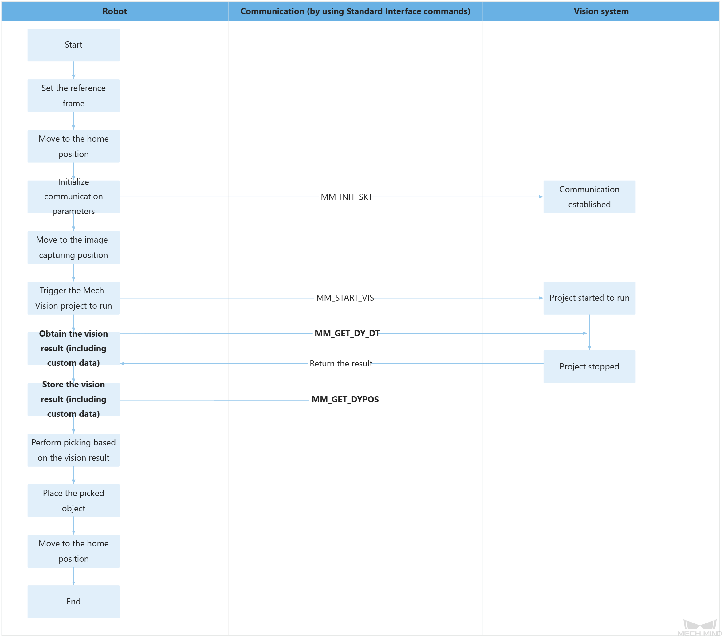
82: PAUSE ;The workflow corresponding to the above example program code is shown in the figure below.
The table below describes the bolded code. You can click the hyperlink to the command name to view its detailed description.
| Feature | Code and description | ||||
|---|---|---|---|---|---|
Obtain the vision result (including the custom data) |
The entire statement indicates that the robot obtains the vision result from the Mech-Vision project with an ID of 1. The vision result includes custom data.
|
||||
Store the vision result (including the custom data) |
The entire statement stores the TCP, label, and custom data of the first vision point in the specified registers. The above code assigns the three pieces of custom data of the vision point (picking waypoint) in R[90], R[91], and R[92] to R[10], R[11], and R[12], respectively.
|