Siemens PLC Client–Siemens SIMATIC S7 PLC (SIMATIC Manager Step7)
This topic provides instructions on setting up the Standard Interface communication based on the Siemens PLC Snap7 protocol between a Siemens SIMATIC S7 PLC and Mech-Vision and Mech-Viz using the SIMATIC Manager STEP7 software.
Hardware and Software Requirements
|
The models and versions listed below are tested and can be used. For other models and versions, you may refer to this guide for operation. If any issues occur, please contact Mech-Mind Technical Support. |
Hardware
-
The following S7 series PLCs from Siemens are supported:
-
S7-300: Integrated PN network port or CP343-1
-
S7-400: Integrated PN network port or CP443-1
-
-
Power adapter of 220V AC to 24V DC
-
IPC or host of Mech-Mind Vision System
-
Ethernet cable
Software
-
Siemens PLC programming software SIMATIC Manager Step7 V5.6
-
Mech-Vision & Mech-Viz versions: 1.7.0 or above
-
Communication interface file between Vision system and S7: MM_Interface_Step7.AWL
The MM_Interface_Step7.AWL file is stored on the Mech-Mind IPC or host. It is located in Communication Component/Robot_Interface/Siemens Snap7/Simatic Manager-STEP7 in the installation directory where Mech-Vision and Mech-Viz are installed.
|
Build and Deploy the PLC Project
Create a PLC Project
-
Open the software SIMATIC Manager, and click the New
 icon in the upper left corner. Enter the project Name and the Storage location in the pop-up window.
Do NOT include Chinese characters in the path name. -
Right-click MM_Camera_Step7, select . After inserting, right-click and select Open Project to enter the hardware configuration interface.

-
Right-click the blank space of the hardware configuration interface, and select to insert the mounting rail.
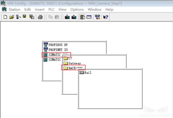
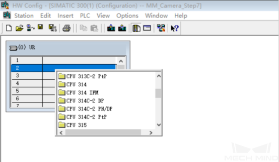
-
Right-click the second row slot of the mounting rail, and select Insert Object, select the module that is consistent with the PLC CPU (the module has to support the PN network port), and the Ethernet Interface Property window will pop up.
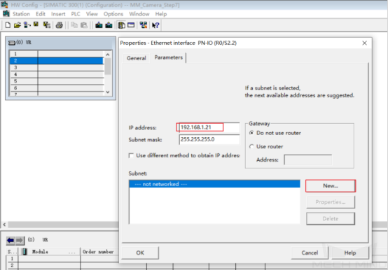
-
After setting the IP address, click New Subnet (the subnet name can be set as the default name), then select the newly created subnet, and click OK.
-
Click Compile and Save
 on the title bar, and close the Hardware Configuration window.
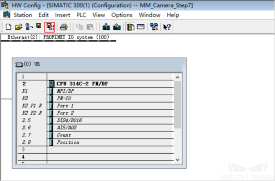
Import the S7 Communication Interface
-
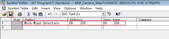
Return to the SIMATIC Manager main interface, select S7 Program, right-click, open the Symbols table, add a new Mech-Mind symbol Interface, and select an unoccupied number for the DB number in the address column.
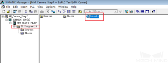
After adding the new symbol, the interface should look like the figure below. Confirm the settings and click Save
 .
.
-
Right-click Sources in the project section on the left, select in turn, select MM_Interface_Step7.AWL in the pop-up window and open it.
The MM_Interface_Step7.AWL file is stored on the Mech-Mind IPC or host. It is located in Communication Component/Robot_Interface/Siemens PLC/Simatic Manager-STEP7in the installation directory where Mech-Vision and Mech-Viz are installed.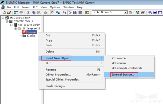
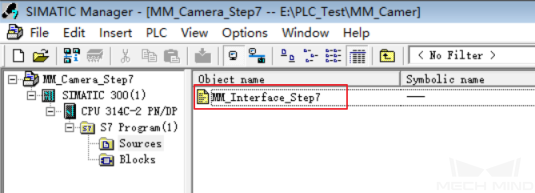
After importing the file, it will look like this:
-
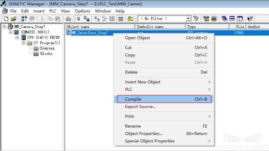
Right-click MM_Interface_Step7, select Compile, and close the window after the compilation is successful.
-
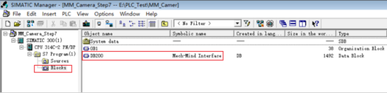
Select Blocks, right-click and select Details, and you can find that Mech-Mind Interface has been imported successfully.
-
Right-click SIMATIC 300 in the project section on the left. Click Download
 on the tool bar to download the project to the CPU.
Configure and Start Communication
Set up Robot Communication Configuration
-
Ensure that the IP address of the IPC is on the same subnet as the PLC, for instance, 192.168.1.10. Open Command Prompt on the IPC and ping the PLC IP address to check if they are connected successfully.
-
Open Mech-Vision, and you may enter different interfaces. Create a new solution according to the instructions below.
-
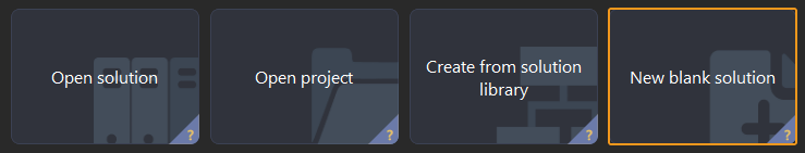
If you have entered the Welcome interface, click New blank solution.
-
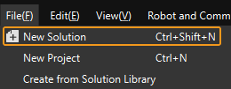
If you have entered the main interface, click on the menu bar.
-
-
Click Robot Communication Configuration on the toolbar of Mech-Vision.
-
In the Robot Communication Configuration window, complete the following configurations.
-
Click the Select robot dropdown, and choose either Listed robot or Custom robot according to the robot used in your project. Then click Next.
-
Listed robot: Suitable for most robots. Click Select robot model to choose the specific robot model.
-
Custom robot: Suitable for gantry robots or robots not included in the listed robot category. Robot Euler angle convention and robot coordinate system need to be selected.
-
-
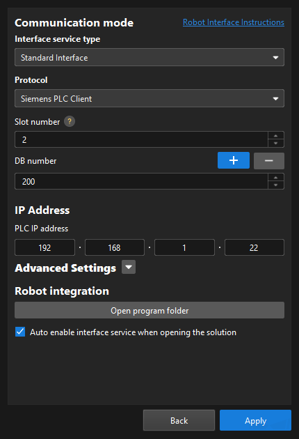
In the Communication mode area, select Standard Interface for Interface service type, and select Siemens PLC Client for Protocol. Set Slot number to 2, and set DB number (i.e. the ID of “Mech-Mind Interface” in the PLC project) to 200.
-
Set the PLC IP address to 192.168.1.21 (i.e. the PLC IP address set previously in SIMATIC Manager)
-
(Optional) Select Auto enable interface service when opening the solution.
-
Click Apply.
-
Start Communication
-
On the main interface of Mech-Vision, make sure that the Robot Communication Configuration switch on the toolbar is flipped and has turned blue. The PLC is successfully connected if the Console tab of Mech-Vision Log panel displays Connect to PLC server successfully. If not, please check the configuration and check whether the physical connection is normal.

-
Start the deployed Mech-Vision and Mech-Viz projects.
-
For the specific usage of DB and interface communication instructions, refer to Siemens PLC. For the usage of the vision system, refer to Siemens PLC Client - Siemens SIMATIC S7 PLC (TIA Portal) Commands.