Example program 2: MM_S2_Viz_Basic
Program Introduction
Description |
The robot triggers the Mech-Viz project to run, and then obtains the planned path for picking and placing. |
||
File path |
You can navigate to the installation directory of Mech-Vision and Mech-Viz and find the file by using the
|
||
Project |
Mech-Vision and Mech-Viz projects |
||
Prerequisites |
|
| This example program is provided for reference only. Before using the program, please modify the program according to the actual scenario. |
Program Description
This part describes the MM_S2_Viz_Basic example program.
MODULE MM_S2_Viz_Basic
!----------------------------------------------------------
! FUNCTION: trigger Mech-Viz project and get planned path
! Mech-Mind, 2023-12-25
!----------------------------------------------------------
!define local num variables
LOCAL VAR num pose_num:=0;
LOCAL VAR num status:=0;
LOCAL VAR num toolid{5}:=[0,0,0,0,0];
LOCAL VAR num vis_pose_num:=0;
LOCAL VAR num count:=0;
LOCAL VAR num label{5}:=[0,0,0,0,0];
!define local joint&pose variables
LOCAL CONST jointtarget home:=[[0,0,0,0,90,0],[9E+9,9E+9,9E+9,9E+9,9E+9,9E+9]];
LOCAL CONST jointtarget snap_jps:=[[0,0,0,0,90,0],[9E+9,9E+9,9E+9,9E+9,9E+9,9E+9]];
LOCAL PERS robtarget camera_capture:=[[302.00,0.00,558.00],[0,0,-1,0],[0,0,0,0],[9E+9,9E+9,9E+9,9E+9,9E+9,9E+9]];
LOCAL PERS robtarget drop_waypoint:=[[302.00,0.00,558.00],[0,0,-1,0],[0,0,0,0],[9E+9,9E+9,9E+9,9E+9,9E+9,9E+9]];
LOCAL PERS robtarget drop:=[[302.00,0.00,558.00],[0,0,-1,0],[0,0,0,0],[9E+9,9E+9,9E+9,9E+9,9E+9,9E+9]];
LOCAL PERS jointtarget jps{5}:=
[
    [[0,0,0,0,0,0],[9E+9,9E+9,9E+9,9E+9,9E+9,9E+9]],
    [[0,0,0,0,0,0],[9E+9,9E+9,9E+9,9E+9,9E+9,9E+9]],
    [[0,0,0,0,0,0],[9E+9,9E+9,9E+9,9E+9,9E+9,9E+9]],
    [[0,0,0,0,0,0],[9E+9,9E+9,9E+9,9E+9,9E+9,9E+9]],
    [[0,0,0,0,0,0],[9E+9,9E+9,9E+9,9E+9,9E+9,9E+9]]
];
!define local tooldata variables
LOCAL PERS tooldata gripper1:=[TRUE,[[0,0,0],[1,0,0,0]],[0.001,[0,0,0.001],[1,0,0,0],0,0,0]];

PROC Sample_2()
    !set the acceleration parameters
    AccSet 50, 50;
    !set the velocity parameters
    VelSet 50, 1000;
    !move to robot home position
    MoveAbsJ home\NoEOffs,v3000,fine,gripper1;
    !initialize communication parameters (initialization is required only once)
    MM_Init_Socket "127.0.0.1",50000,300;
    !move to image-capturing position
    MoveL camera_capture,v1000,fine,gripper1;
    !open socket connection
    MM_Open_Socket status;
    IF status = 3099 THEN
        TPWrite "MM: Communication Error";
        STOP;
    ENDIF
    !trigger Mech-Viz project
    MM_Start_Viz 2,snap_jps,status;
    IF status <> 2103 THEN
        !add error handling logic here according to different error codes
        TPWrite "MM: Status Error";
        STOP;
    ENDIF
    !get planned path, 1st argument (1) means getting pose in JPs
    MM_Get_VizData 1, pose_num, vis_pose_num, status;
    !check whether planned path has been got from Mech-Viz successfully
    IF status <> 2100 THEN
        !add error handling logic here according to different error codes
        !e.g.: status=2038 means no point cloud in ROI
        Stop;
    ENDIF
    !close socket connection
    MM_Close_Socket;
    !save waypoints of the planned path to local variables one by one
    MM_Get_Jps 1,jps{1},label{1},toolid{1};
    MM_Get_JPS 2,jps{2},label{2},toolid{2};
    MM_Get_JPS 3,jps{3},label{3},toolid{3};
    !follow the planned path to pick
    !move to approach waypoint of picking
    MoveAbsJ jps{1},v1000,fine,gripper1;
    !move to picking waypoint
    MoveAbsJ jps{2},v300,fine,gripper1;
    !add object grasping logic here, such as "setdo DO_1, 1;"
    Stop;
    !move to departure waypoint of picking
    MoveAbsJ jps{3},v1000,fine,gripper1;
    !move to intermediate waypoint of placing
    MoveJ drop_waypoint,v1000,z50,gripper1;
    !move to approach waypoint of placing
    MoveL RelTool(drop,0,0,-100),v1000,fine,gripper1;
    !move to placing waypoint
    MoveL drop,v300,fine,gripper1;
    !add object releasing logic here, such as "setdo DO_1, 0;"
    Stop;
    !move to departure waypoint of placing
    MoveL RelTool(drop,0,0,-100),v1000,fine,gripper1;
    !move back to robot home position
    MoveAbsJ home\NoEOffs,v3000,fine,gripper1;
ENDPROC
ENDMODULE
The workflow corresponding to the above example program code is shown in the figure below.
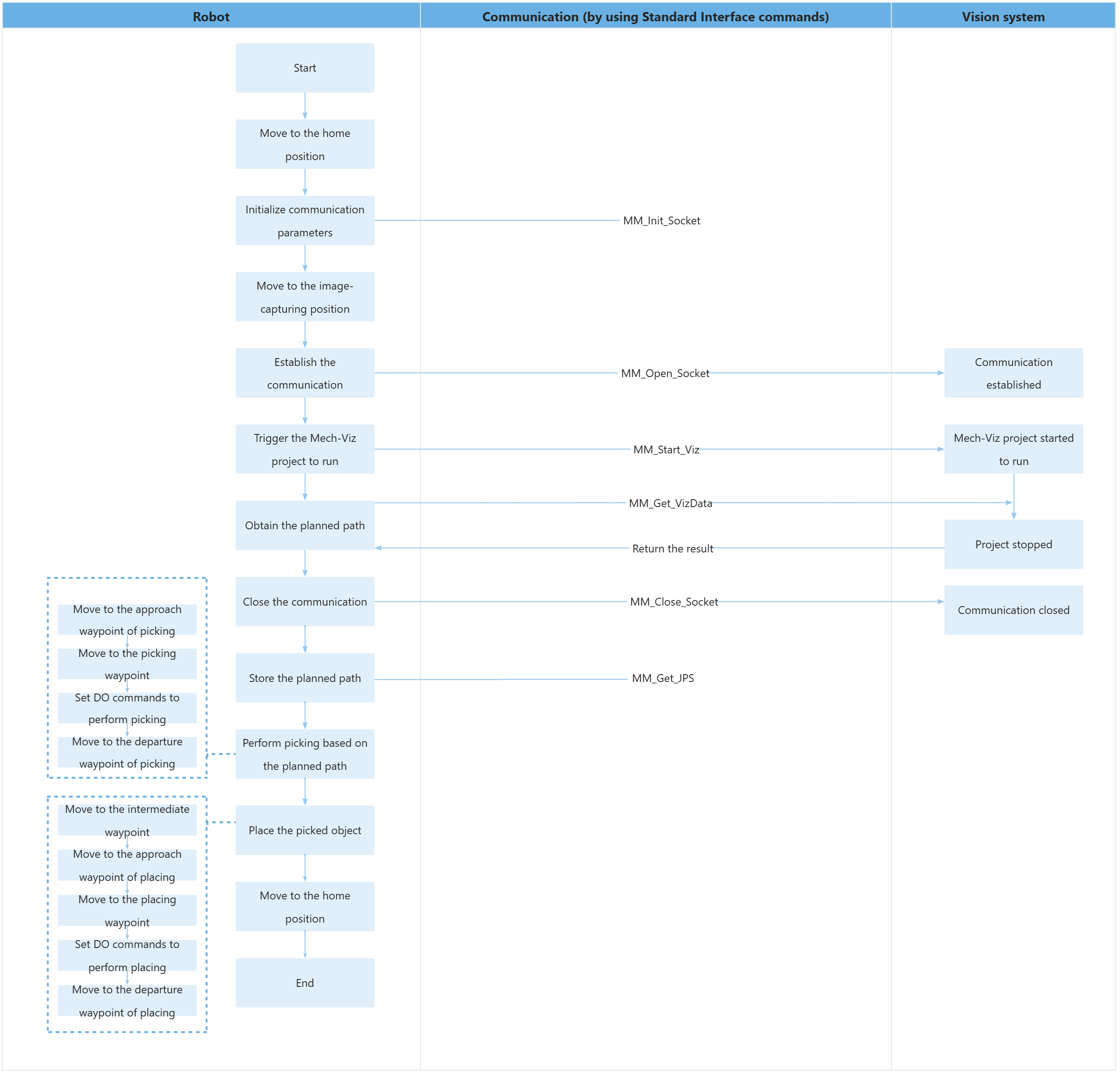
The table below explains the above program. You can click the hyperlink to the command name to view its detailed description.
| Feature | Code and description | ||
|---|---|---|---|
Define variables |
Define local variables. The above local variables are only valid in this program. Teach the home position (home variable), the pose of the input Mech-Viz project (snap_jps variable), the image-capturing position (camera_capture variable), the intermediate waypoint of placing (drop_waypoint variable), and the placing waypoint (drop variable), and set the tool data (gripper1 variable) in advance.
|
||
Set the acceleration and velocity |
|
||
Move to the home position |
Therefore, the entire command indicates that the robot moves to the home position in the TEACH mode without the impact of external axes at a speed of 3000 mm/s. |
||
Initialize communication parameters |
The robot sends the MM_Init_Socket command to set the IP address, port number, and timeout period of the communication object (the IPC) to 127.0.0.1, 50000, and 300 seconds.
|
||
Move to the image-capturing position |
Therefore, the entire command indicates that the robot moves to the image-capturing position accurately in linear motion, with a velocity of 1000 mm/s. |
||
Establish the communication |
The TCP communication between the robot and the vision system is established by using the MM_Open_Socket command. When the status code is 3099, the robot has successfully obtained all vision result. Otherwise, an error has occurred in the vision system. You can perform the corresponding operation based on the specific error code. |
||
Trigger the Mech-Viz project to run |
The entire command indicates that the robot triggers the vision system to run the Mech-Viz project, and then Mech-Viz plans the robot’s picking path base on the vision result output by Mech-Vision. When the status code is 2103, the robot has successfully obtained the planned path. Otherwise, an error has occurred in the vision system. You can perform the corresponding operation based on the specific error code. |
||
Get the planned path |
The entire statement indicates that the robot obtains the planned path from the Mech-Viz project.
When the status code is 2100, the robot has successfully obtained the planned path. Otherwise, an error has occurred in the vision system. You can perform the corresponding operation based on the specific error code. |
||
Close the communication |
The TCP communication between the robot and the vision system is closed by using the MM_Close_Socket command. |
||
Store the planned path |
The entire command “MM_Get_JPS 1,jps{1},label{1},toolid{1};” stores the joint positions, label, and tool ID of the first waypoint in the specified variables.
|
||
Move to the approach waypoint of picking |
The robot moves to the approach waypoint of picking (the position represented by jps{1}). |
||
Move to the picking waypoint |
The robot moves to the picking waypoint (the position represented by jps{2}). |
||
Set DOs to perform picking |
After the robot moves to the picking waypoint, you can set a DO (such as setdo DO_1, 1;) to control the robot to use the tool to perform picking. Please set DOs based on the actual situation.
|
||
Move to the departure waypoint of picking |
The robot moves to the departure waypoint of picking (the position represented by jps{3}). |
||
Move to the intermediate waypoint |
The entire command moves the robot in joint positions to a certain intermediate waypoint between the departure waypoint of picking and the approach waypoint of placing, with a velocity of 1000 mm/s and a blend radius of 50 mm.
|
||
Move the robot to the approach waypoint of placing |
The entire command moves the robot to 100 mm above the placing waypoint to reach the approach waypoint of placing.
|
||
Move to the placing waypoint |
The robot moves from the approach waypoint of placing to the placing waypoint. |
||
Set DOs to perform placing |
After the robot moves to the placing waypoint, you can set a DO (such as setdo DO_1, 0;) to control the robot to use the tool to perform placing. Please set DOs based on the actual situation.
|
||
Move the robot to the departure waypoint of placing |
The robot moves to 100 mm above the placing waypoint and reaches the departure waypoint of placing.
|
||
Move to the home position |
The robot moves from the departure waypoint of placing to the home waypoint again. |