Communication Configuration and Example Program Usage
This topic provides instructions on setting up the Standard Interface communication based on the Modbus TCP protocol between a Mitsubishi MELSEC-Q Series PLC and the Mech-Mind Vision System.
Hardware and Software Requirements
|
The models and versions listed below are tested and can be used. For other models and versions, you may refer to this guide for operation. If any issues occur, please contact Mech-Mind Technical Support. |
Hardware
-
CPU: MELSEC-Q Series Q03UDVCPU
-
Power supply: Mitsubishi Q61P; Base unit: Mitsubishi Q33B
-
Mech-Mind Vision System IPC or host PC
-
USB Type A male to USB Mini-B male cable
-
Ethernet cables
Software
-
Mitsubishi PLC Engineering Software: GX Works2
-
Mech-Vision & Mech-Viz versions: 2.0.0 or above
-
PLC example program files:
-
MODBUS_TCP_Protocol Configuration.tpc (used to establish communication via Modbus TCP/IP)
-
MODBUS TCP_Q_Simple_Label.GXW (used to implement the features of various interface commands)
The example programs are stored in
Communication Component/Robot_Interface/Modbus TCP/MITSUBISHI Q serialin the installation directory where Mech-Vision and Mech-Viz are installed. Please copy and paste the example programs to a PC with GX Works2 installed. -
| The firewall on the IPC must be turned off. |
Configure IPC and Initiate Communication
Set IP Address of the IPC
-
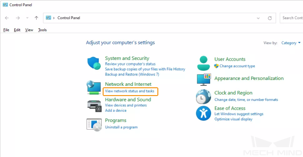
Open the Control Panel, and click View network status and tasks.
-
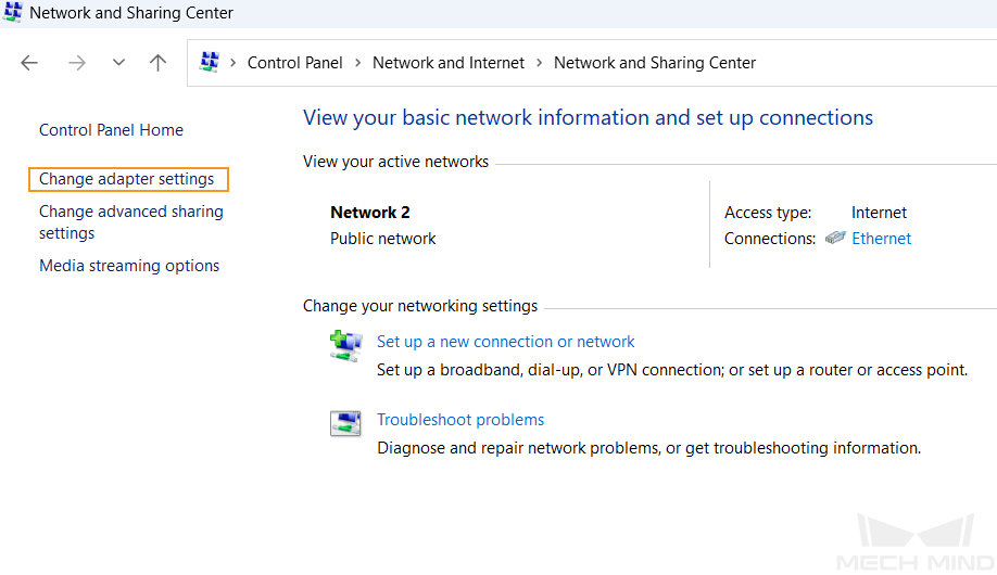
In the “Network and Sharing Center” window, click Change adapter settings.
-
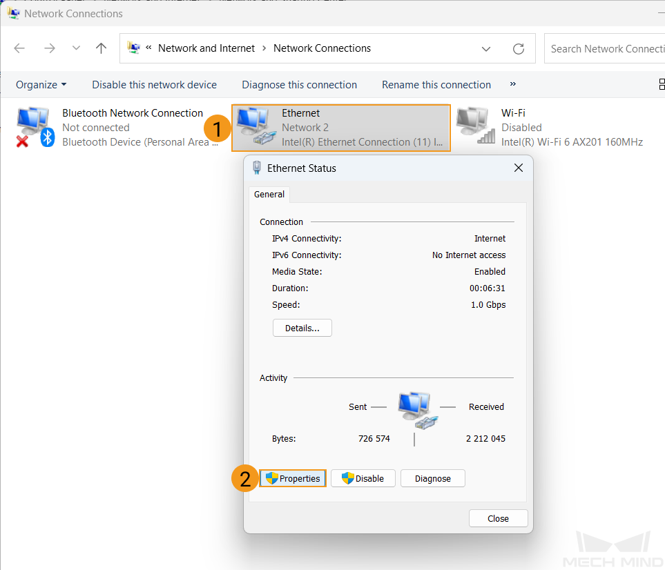
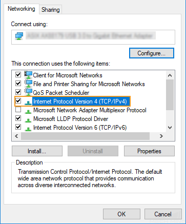
In the “Network Connections” window, double-click the Ethernet interface connected to the PLC, and select Properties in the pop-up Ethernet Status window.
-
In the Ethernet Properties window, select Networking in the menu bar, and double-click Internet Protocol Version 4(TCP/IPv4).
-
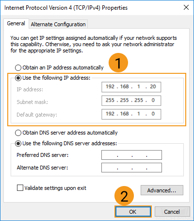
In the Internet Protocol Version 4 (TCP/IPv4) window, select “Use the following IP address”, and set the IP address, subnet mask and default gateway (must be in the same subnet as the PLC). Then, click “OK” to save the changes.
Set up Robot Communication Configuration
-
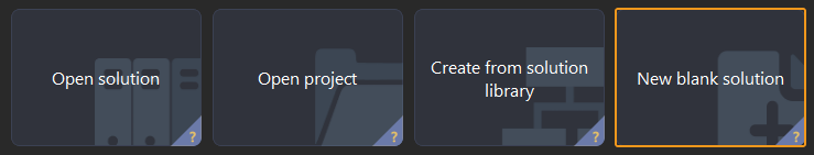
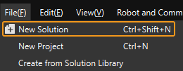
Open Mech-Vision, and you may enter different interfaces. Create a new solution according to the instructions below.
-
If you have entered the Welcome interface, click New blank solution.
-
If you have entered the main interface, click on the menu bar.
-
-
Click Robot Communication Configuration on the toolbar of Mech-Vision.
-
In the Robot Communication Configuration window, complete the following configurations.
-
Click the Select robot dropdown, and choose either Listed robot or Custom robot according to the robot used in your project. Then click Next.
-
Listed robot: Suitable for most robots. Click Select robot model to choose the specific robot model.
-
Custom robot: Suitable for gantry robots or robots not included in the listed robot category. Robot Euler angle convention and robot coordinate system need to be selected.
-
-
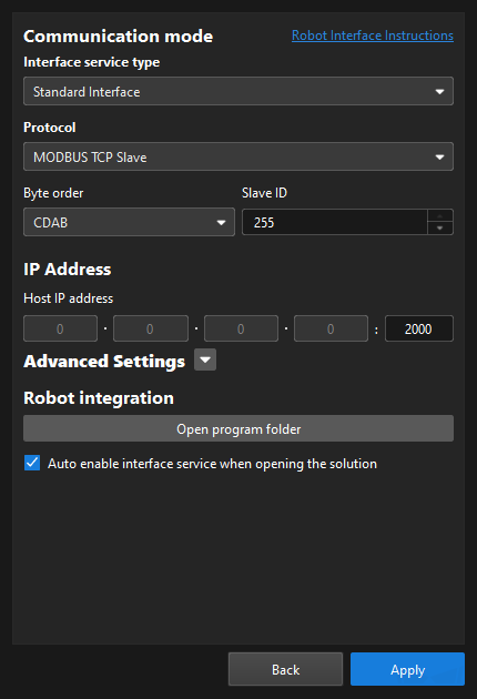
In the Communication mode area, select Standard Interface for Interface service type, MODBUS TCP Slave for Protocol, and CDAB for Byte order. Set the Slave ID to 255.
-
Set the port number to 2000 for the host IP address.
-
(Optional) Select Auto enable interface service when opening the solution.
-
Click Apply.
-
-
On the main interface of Mech-Vision, make sure that the Robot Communication Configuration switch on the toolbar is flipped and turned to blue.

Create and Configure the PLC Project
Create a PLC Project
-
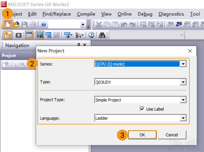
Open GX Works2, and click the New icon on the toolbar. In the New Project window, select QCPU (Q mode) as the Series, Q03UDV as the Type, Simple Project as the Project Type. Select Use Label, and select Ladder as the language. After setting, click OK to save changes.
-
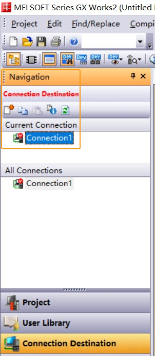
Go to , and double-click Connection1.
-
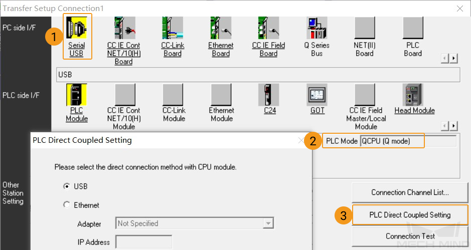
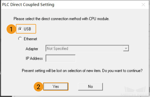
A Transfer Setup Connection1 window will pop up. Select Serial USB in the PC side I/F panel, and select QCPU (Q mode) as the PLC mode. Then click PLC Direct Coupled Setting.
-
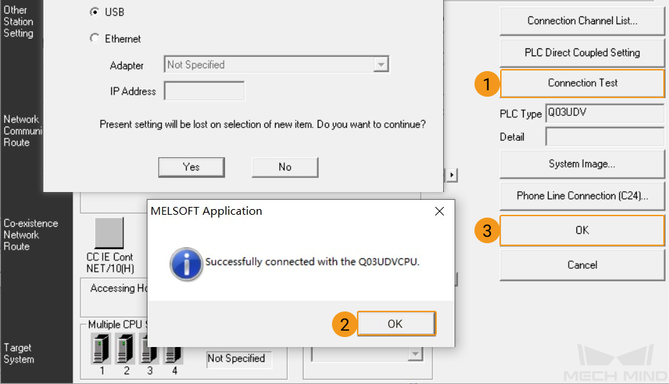
In the pop-up window, select USB and click Yes.
-
Go back to the Transfer Setup Connection1 window, click Connection Test. If GX Works2 is connected with the PLC successfully, a message saying “Successfully connected with the Q03UDVCPU” will pop up. Click OK to dismiss this message. Then, in the Transfer Setup Connection1 window, click OK to go back to the main interface of GX Works2.
-
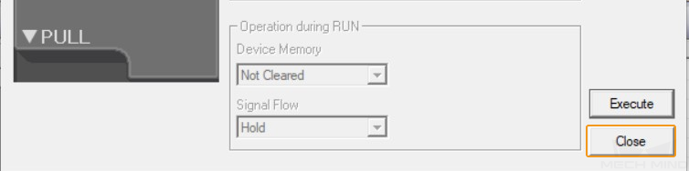
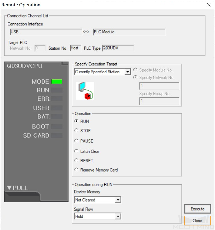
Click Online in the menu bar and then select Remote Operation.

-
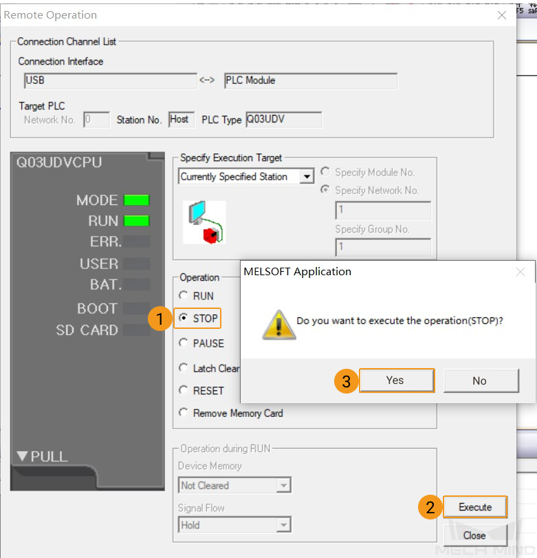
A Remote Operation window will pop up, select STOP as the Operation type, and click Execute. A message saying that “Do you want to execute the operation(STOP)” will pop up. Select Yes in the window.
-
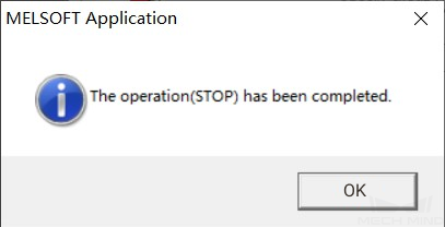
A message saying that “The operation(STOP) has been completed” will pop up. Select OK in the window.
-
Click Close in the Remote Operation window and go back to the main interface of GX Works2.
Configure Communication Parameters of Modbus TCP
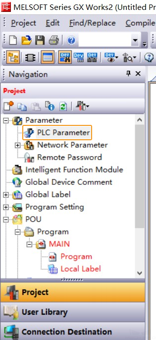
-
Go to , and double-click PLC Parameter.
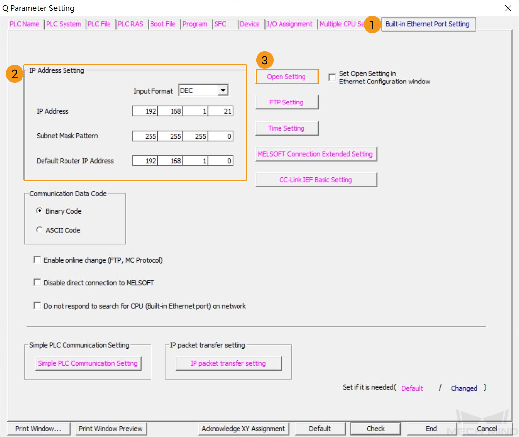
-
In the pop-up Q Parameter Setting window, click the Built-in Ethernet Port Setting tab, and set the IP address, subnet mask, and default router IP address in the IP Address Setting area. Then, click Open Settings. Then, a Built-in Ethernet Port Open Setting window will pop up.
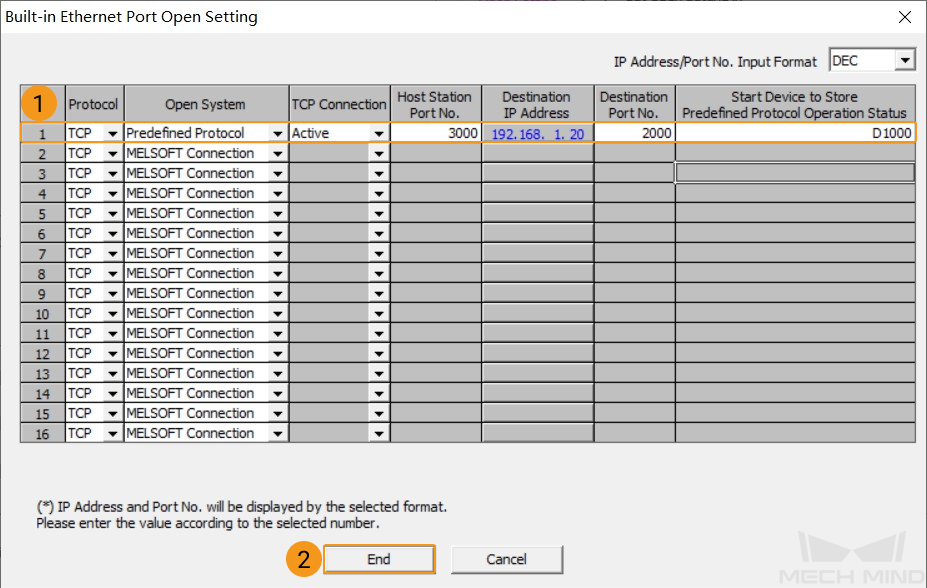
-
In the pop-up window, configure the parameters on the first line as shown in the figure below. Then, click End and return to the Q Parameter Setting window, and then click End to return to the main interface of GX Works2.
-
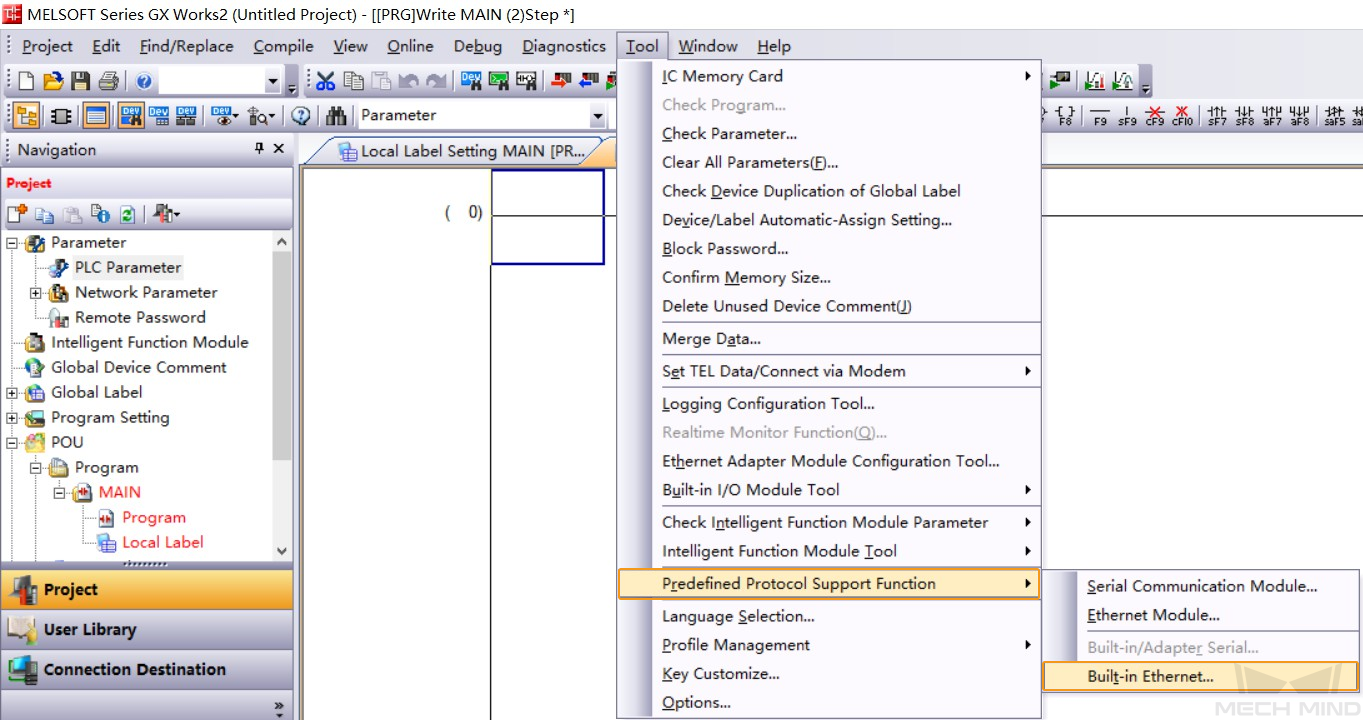
In the GX Works2 software window, click Tool in the menu bar, and select , and open the Predefined Protocol Support Function-Built-in Ethernet window.
-
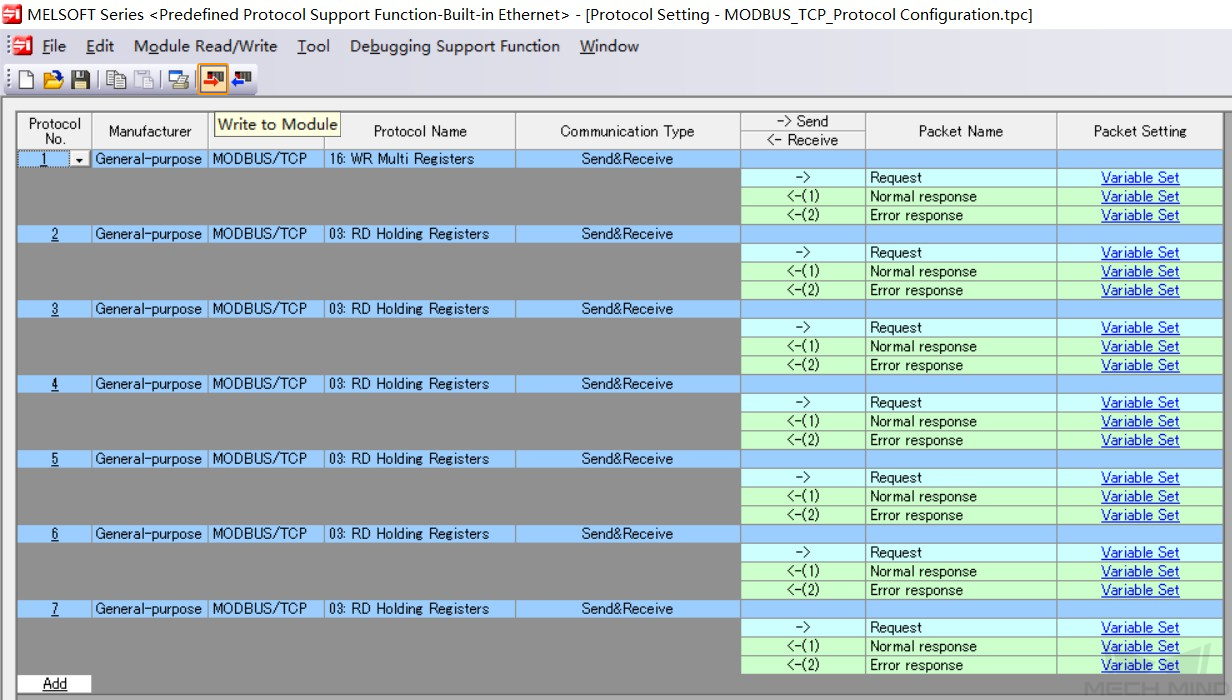
In the Predefined Protocol Support Function-Built-in Ethernet window, click the open icon. Locate and select the Modbus TCP communication configuration file
MODBUS_TCP_Protocol Configuration.tpc, and click Open.
-
In the Predefined Protocol Support Function-Built-in Ethernet window, click the Write to Module icon.
-
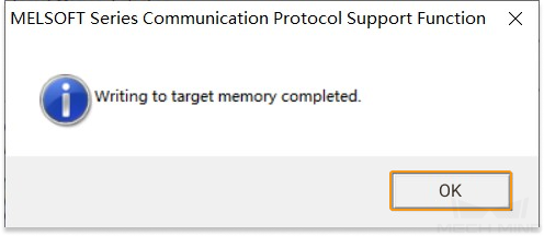
In the pop-up Module Write window, click Execute. If a pop-up message saying “Protocol setting file already exists in target memory. Do you want to overwrite?” pops up, click Yes.

-
A message saying “Writing to target memory completed.” will pop up if the writing has been completed successfully. Click OK in the window.
Import Mech-Mind Example Programs
| Before you add the example program to a project already in use, it is recommended to import it to a new project and test it first. |
-
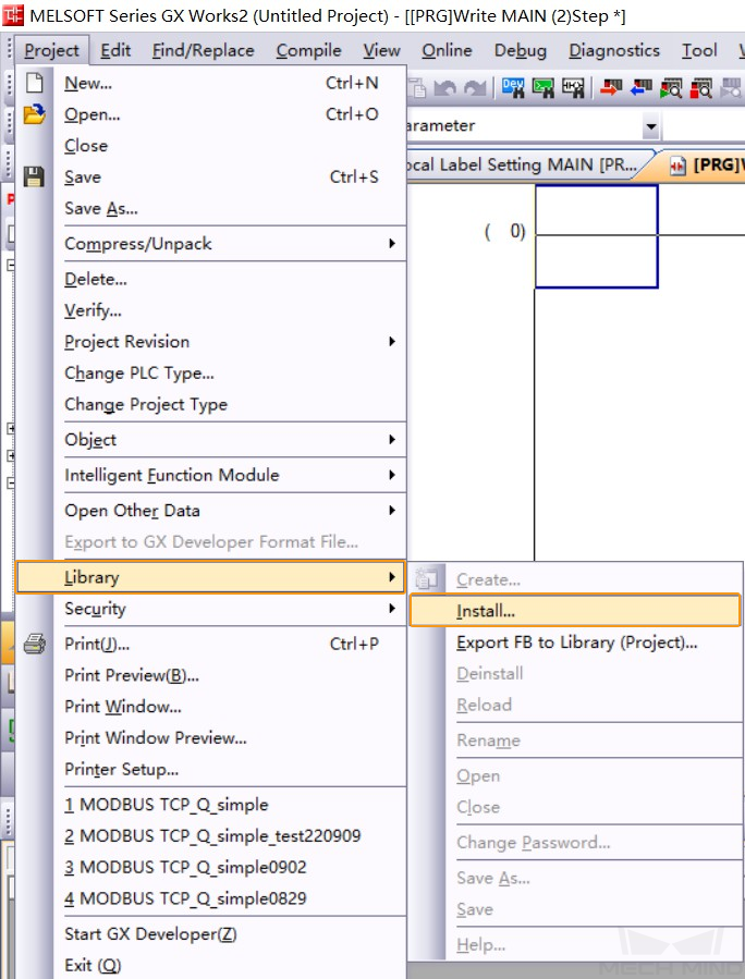
Go back to the main interface of GX Works2. In the toolbar, navigate to .
-
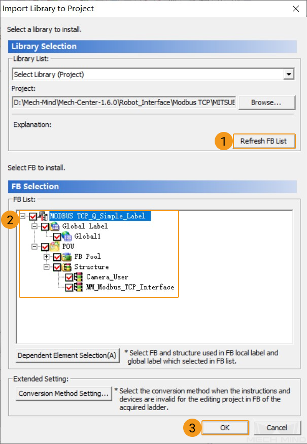
In the pop-up Import Library to Project window, select Select Library (Project) for Library List, and click Browse to locate the local
MODBUS TCP_Q_Simple_Label.GXWfile. Select the file and click Open.
-
In the Import Library to Project window, click Refresh FB List. In the Select FB to install area, select all items in the FB List, and then click OK.
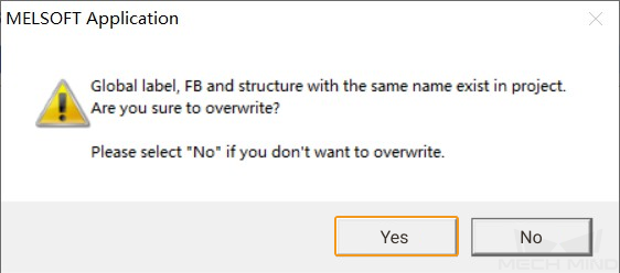
-
A message saying “Are you sure to overwrite?” will pop up. Select Yes in the window and go back to the main interface of GX Works2.
-
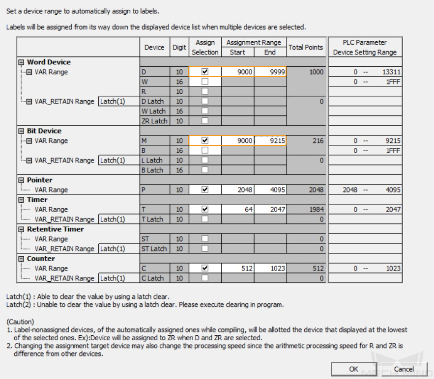
In the GX Works2 software window, go to .

-
In the pop-up window, modify the Assignment Range of Word Device D, and then click OK.
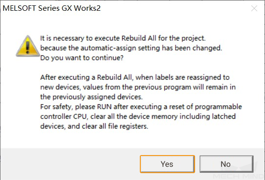
-
Select Yes in the pop-up window to continue, and return to the GX Works2 software window.
Build Program and Download to PLC
-
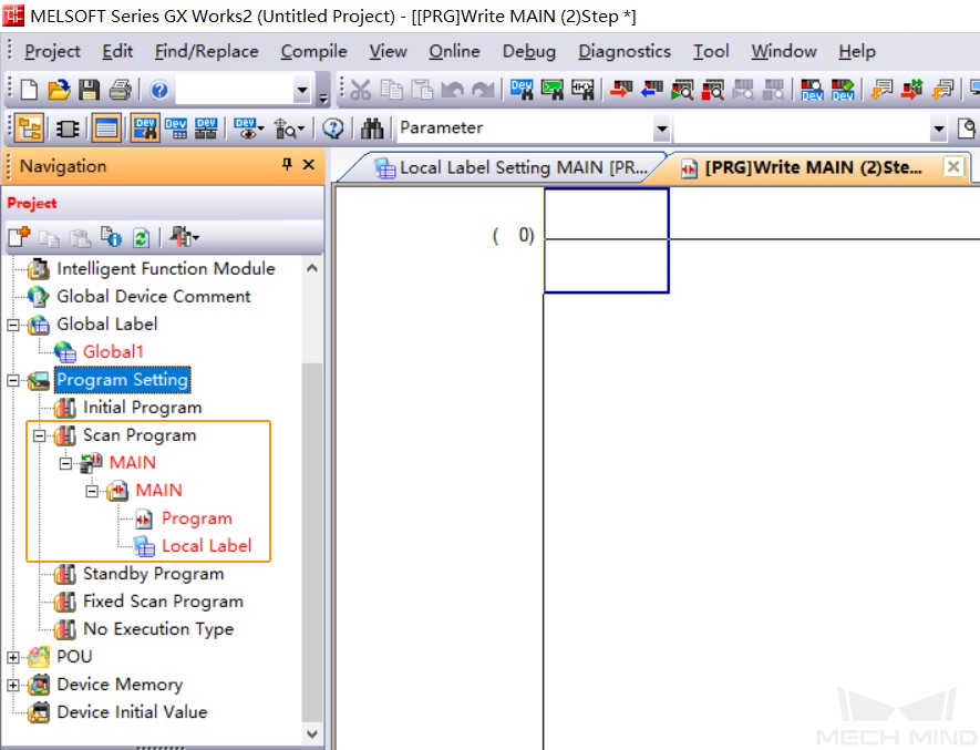
In GX Works2, expand the Program Setting in the Navigation, drag the MAIN under No Execution Type to Scan Program. Then double-click Program.
-
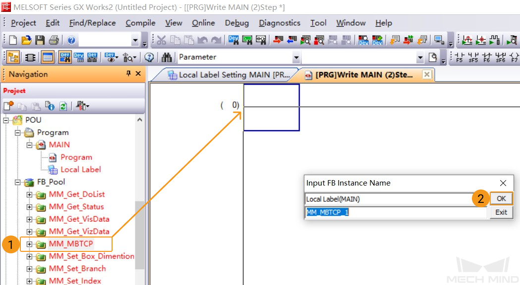
Expand POU ‣ FB_Pool and drag MM_MBTCP to line 0 of MAIN. An Input FB Instance Name window will pop up. Keep the default settings and click OK.
-
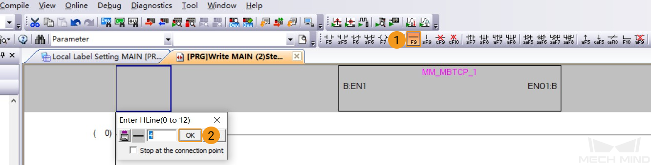
Click the Horizontal Line icon in the toolbar. Click OK in the pop-up window to connect the left bus line with the EN1 input port of the FB.
-
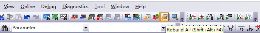
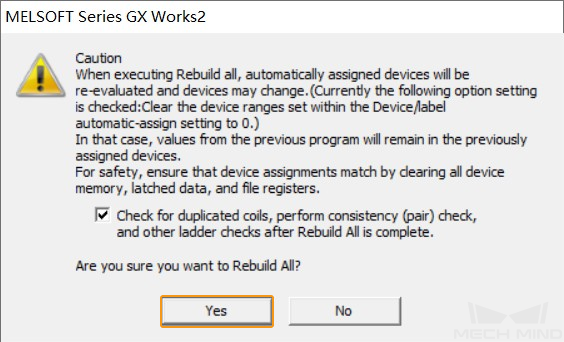
Click the Rebuild All icon in the toolbar.
-
In the pop-up window asking “Are you sure you want to Rebuild All?”, click Yes.
-
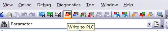
Click the Write to PLC icon in the toolbar.
-
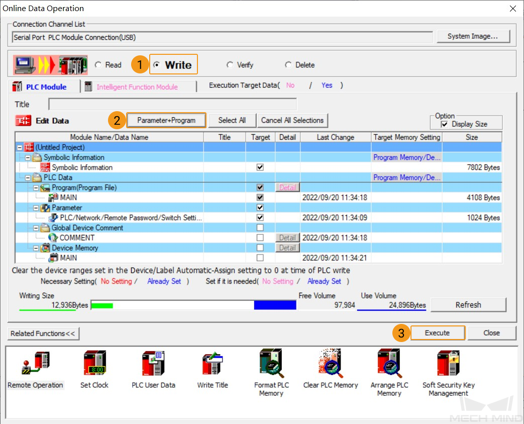
An Online Data Operation window will pop up. Select Write, click Parameter+Program, and click Execute.
-
Click Yes in the pop-up window as shown below.

-
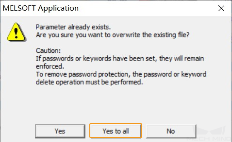
Select Yes to all for “Are you sure you want to overwrite the existing file?”.
-
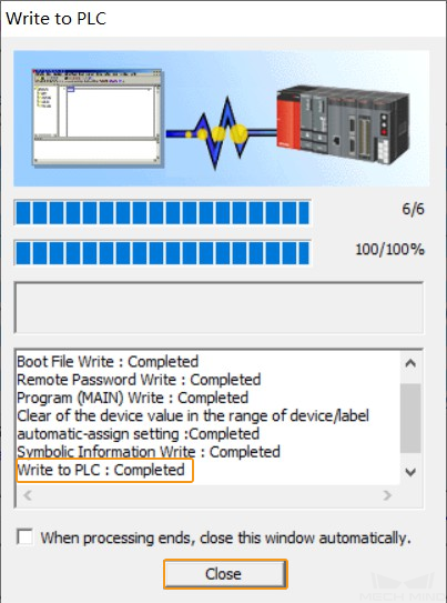
In the Write to PLC window, when “Write to PLC: Completed” appears in the panel, click Close.
-
Click Online in the menu bar and select Remote Operation.
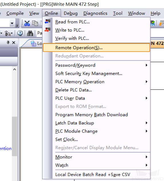
-
In the Remote Operation window, select RUN as the Operation type, and click Execute.

-
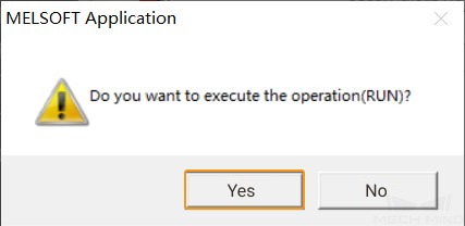
A message saying “Do you want to execute the operation(RUN)” will pop up. Select Yes in the window.
-
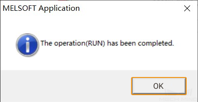
A message saying “The operation(RUN) has been completed.” will pop up. Select OK in the window.
-
Click Close in the Remote Operation window and go back to the main interface of GX Works2.
Check Communication
-
Click the Start Monitoring (All Windows) icon on the toolbar.
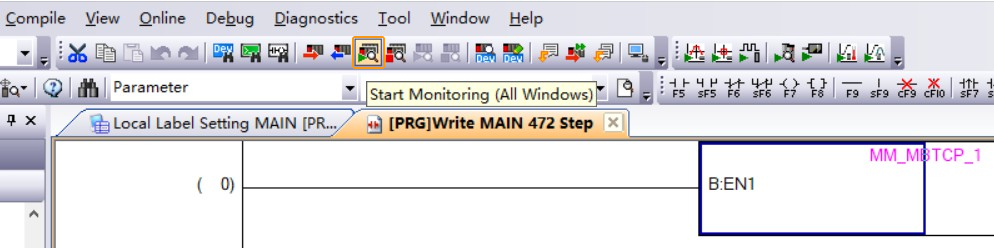
-
Click Yes in the pop-up window as shown below.

-
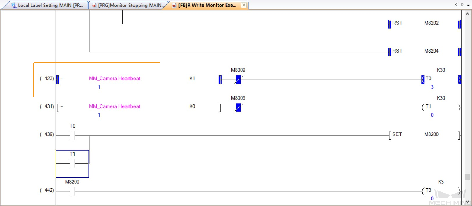
Double-click MM_MBTCP on line 0 of MAIN, and scroll to line 423 of the program. If the connection is successful, the monitored value of MM_Camera.Heartbeat will be changing constantly.
-
The PLC is successfully connected if the following message is displayed in the Console tab of Mech-Vision Log panel: client connected. If you don’t see this log message, please check:
-
If the hardware is properly connected;
-
If the Interface Service has been started successfully in Mech-Vision;
-
If the PLC program has been successfully downloaded to the PLC.
-
Test with Mech-Vision/Mech-Viz Project
This section introduces how to use the example program FB to trigger the Mech-Vision project to obtain vision points and trigger the Mech-Viz project to obtain the planned path.
Prerequisites
-
Return to Mech-Vision and create a Mech-Vision project. Right-click the solution and select Autoload Solution. Projects in the solution are also autoloaded. Meanwhile, the project number will show up before each project name.
-
Create Mech-Viz project: Right-click the project name in Resources in Mech-Viz and select Autoload Project.
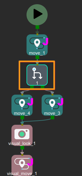
The Mech-Viz project used for testing should contain a “Branch by Msg” Step that has been renamed to 1 as shown below.
Run Mech-Vision Project and Obtain Vision Points
Configure Programs
-
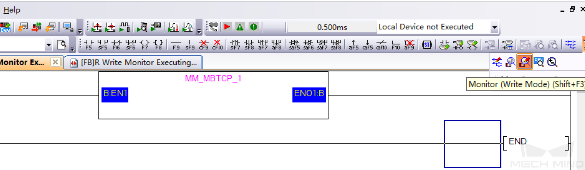
In GX Works2, under the Navigation/Project, click the Monitor (Write Mode) icon in the toolbar.
-
A window saying “Execute the command below when mode is changed.” will pop up. Click OK in the window.

-
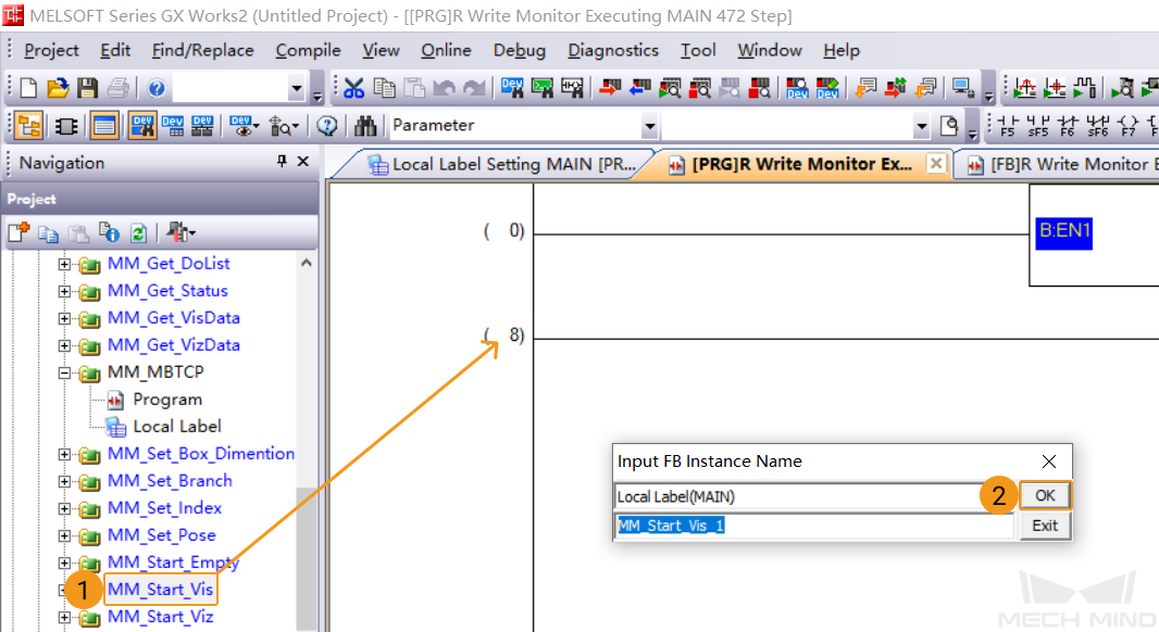
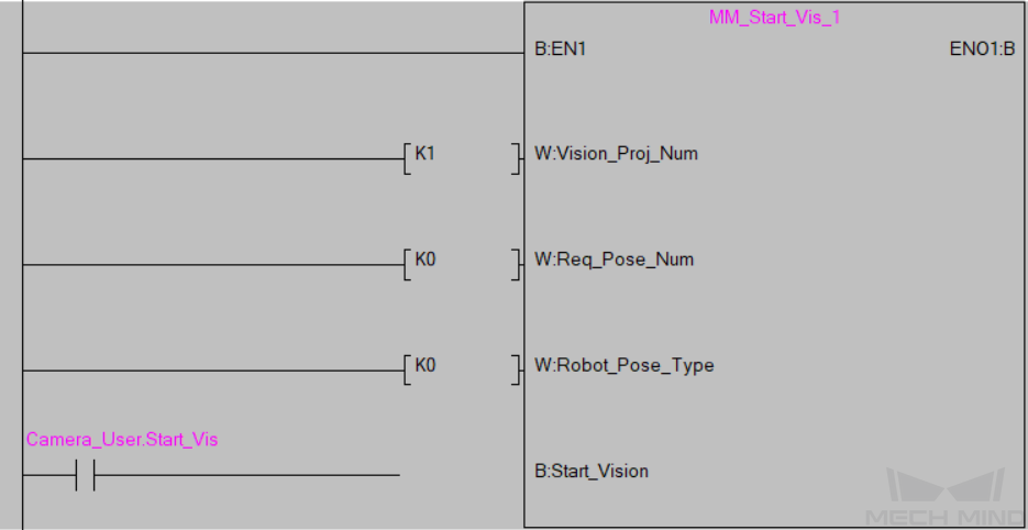
Expand POU/FB_Pool and drag MM_Start_Vis to line 8 of MAIN. An Input FB Instance Name window will pop up. Keep the default settings and click OK.
-
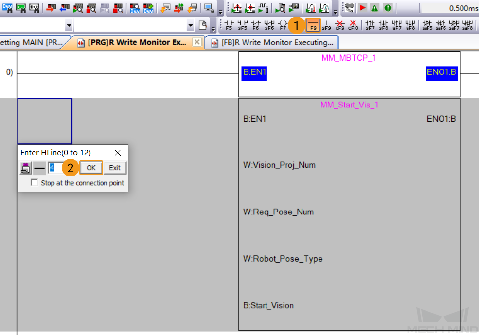
Click Horizontal Line icon in the toolbar. Click OK in the pop-up window to connect the left bus line with the EN1 input port of the FB.
-
Set Mech-Vision project ID, namely, the number before the project name in the project list in Mech-Vision. set the port value of Vision_Proj_Num to 1, and project No. 1 in Mech-Vision will run.
-
Set the number of poses to be sent by Mech-Vision project. set the port value of Req_Pose_Num to 0, and all poses in the vision result will be returned from Mech-Vision.
-
Set the type of pose to be sent by the robot. Setting the value of Robot_Pose_Type to 0 indicates that the project is in the Eye-to-Hand mode, and the image-capturing pose is not needed.
-
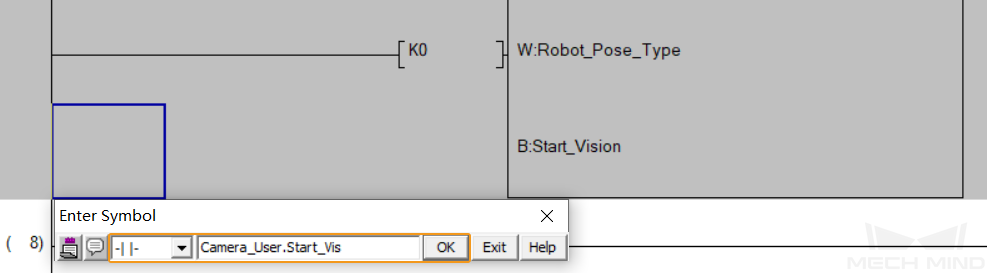
Double-click the blue frame area on the left of Start_Vision port of MM_Start_Vis FB. Select Open Contact in the pop-up window, and enter the global label Camera_User.Start_Vis. Then click OK to connect the Start_Vision port with the bus line on the left.
-
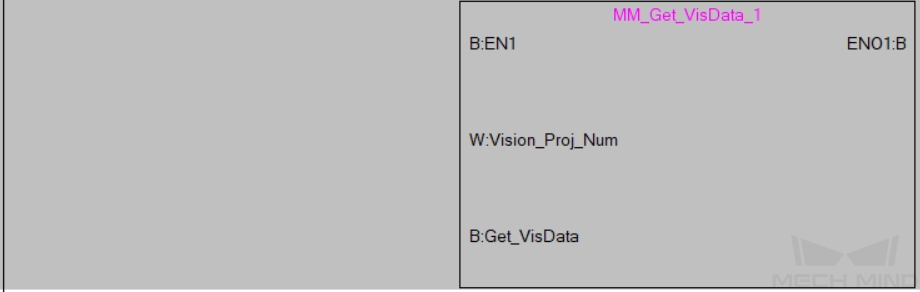
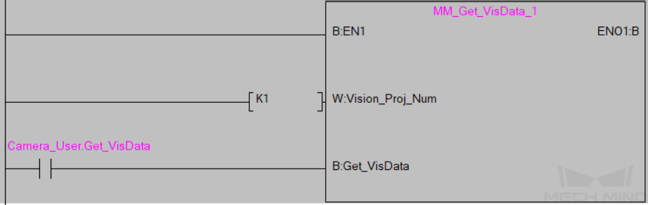
Drag MM_Get_VisData to line 8 of MAIN. An Input FB Instance Name window will pop up. Keep the default settings and click OK. Click Horizontal Line icon in the toolbar, and click OK in the pop-up window to connect the left bus line with the EN1 input port of the FB.
-
Set Mech-Vision project ID, namely, the number before the project name in the project list in Mech-Vision. Set the port value of Vision_Proj_Num to 1, and the vision recognition result of Project No.1 in Mech-Vision will be obtained.
-
Double-click the blue frame area on the left of Get_VisData port of MM_Get_VisData FB. Select Open Contact in the pop-up window, and enter the global label Camera_User.Get_VisData. Then click OK to connect the Get_VisData port with the bus line.
-
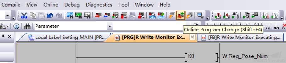
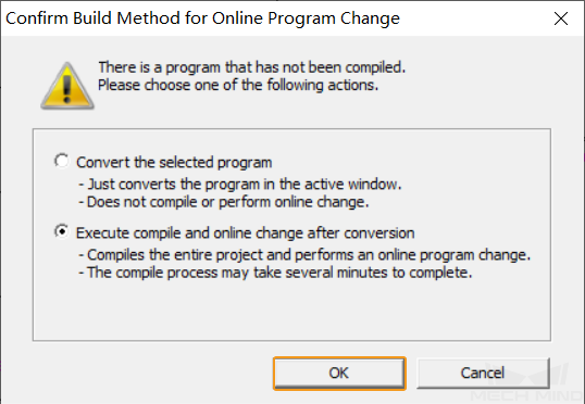
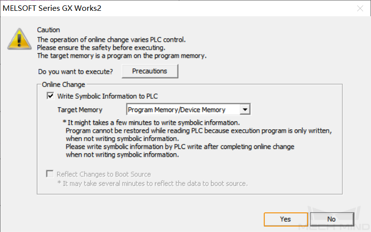
Click the Online Program Change icon in the toolbar.
-
Click OK in the pop-up Confirm Build Method for Online Program Change window.
-
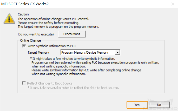
Click Yes in the pop-up window as shown below.
-
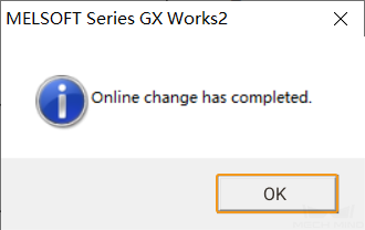
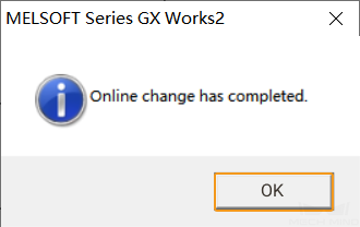
Lastly, click OK to complete downloading the program to PLC.
Trigger Mech-Vision Project to Run
-
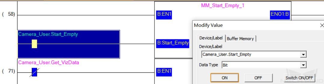
In the interface of MAIN, right-click the input variable Camera_User.Start_Vis of MM_Start_Vis FB, and select .
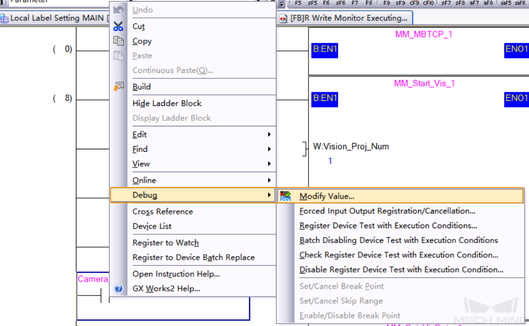
-
In the pop-up Modify Value window, click ON to trigger the Mech-Vision project to run. Then click OFF to reset the value.
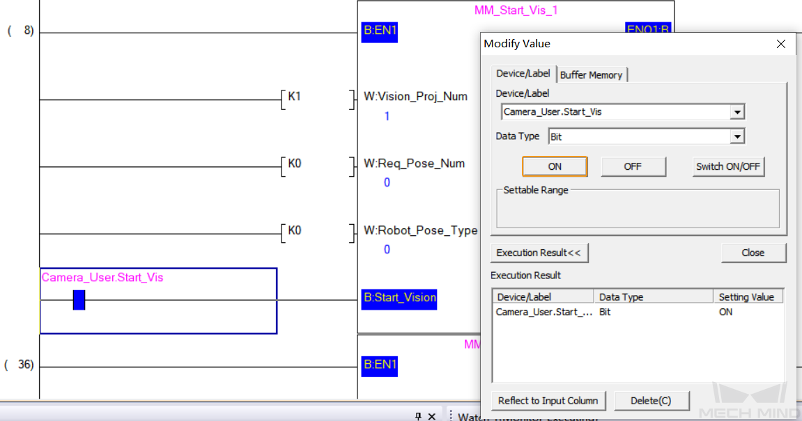
-
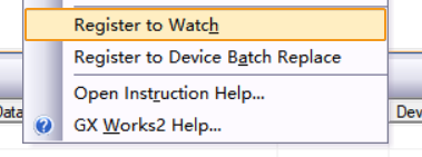
Right-click the blank space, select Register to Watch, and enter the global label MM_Camera.Status_Code. If the project is started successfully, the status code 1102 will be returned. Otherwise, the corresponding error code will be returned. Please refer to Status Codes and Troubleshooting for troubleshooting.
Obtain Vision Points from Mech-Vision
-
Select the input variable Camera_User.Get_VisData of MM_Get_VisData FB, and click ON in the pop-up window to obtain vision points. Then click OFF to reset the value.
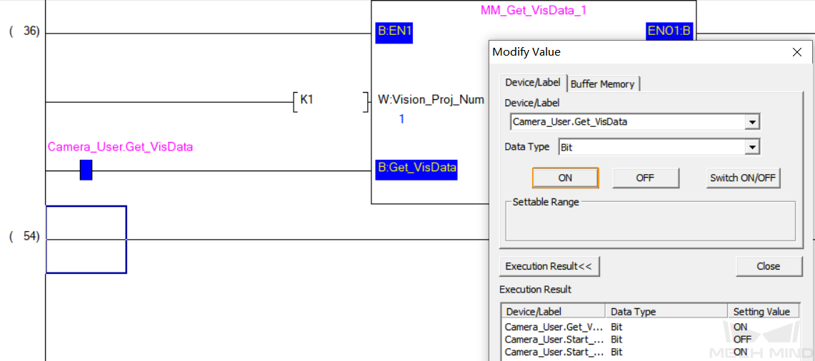
-
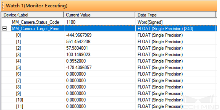
Right-click the blank space, select Register to Watch, and enter the global label MM_Camera.Status_Code. If the vision points are obtained successfully, the status code 1100 will be returned. Otherwise, the corresponding error code will be returned. Please refer to Status Codes and Troubleshooting for troubleshooting. Then, enter the global label MM_Camera.Target_Pose, and the pose data of vision points will be returned.
Run Mech-Viz Project and Obtain Planned Path
Configure Programs
-
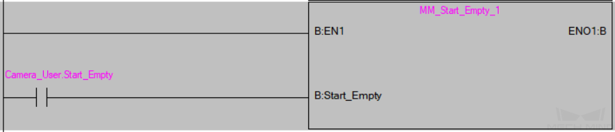
Drag MM_Start_Empty to line 54 of MAIN. An Input FB Instance Name window will pop up. Keep the default settings and click OK. Click Horizontal Line icon in the toolbar to connect the left bus line with the EN1 input port of the FB.

-
Double-click the blue frame area on the left of Start_Empty port of MM_Start_Vis FB. Select Open Contact in the pop-up window, and enter the global label Camera_User.Start_Empty. Then click OK to connect the Start_Empty port with the bus line.
-
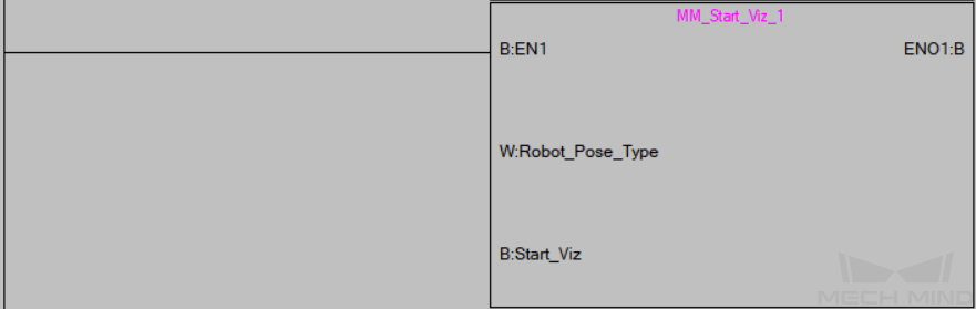
Drag MM_Start_Viz, MM_Set_Branch, and MM_Get_VizData to line 54 of MAIN respectively. An Input FB Instance Name window will pop up. Keep the default settings and click OK. Click Horizontal Line icon in the toolbar to connect the left bus line with the EN1 input port of the FB.

-
Set the type of pose to be sent by the robot. Setting the value of Robot_Pose_Type to 0 indicates that the project is in the Eye-to-Hand mode, and the image-capturing pose is not needed.
-
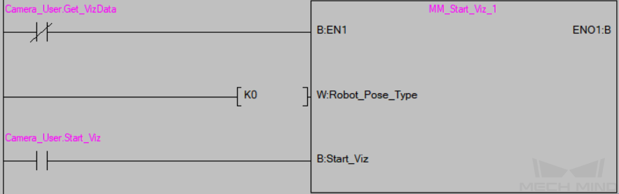
Double-click the blue frame area on the left of EN1 port of MM_Start_Viz FB. Select Close Contact in the pop-up window, and enter the global label Camera_User.Get_VizData. Then, click OK to connect the EN1 port with the left bus line.
-
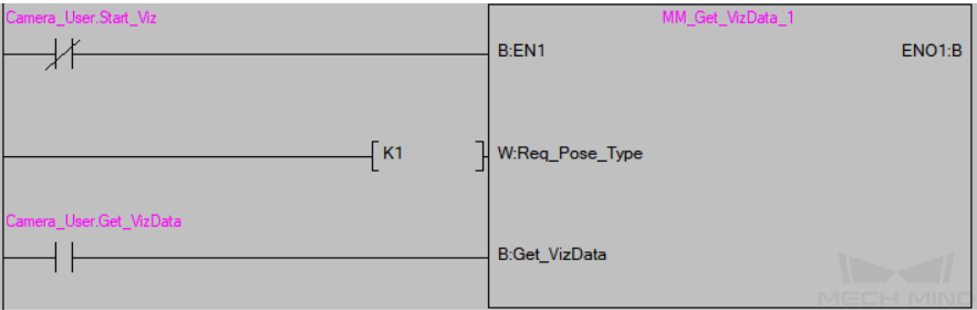
Double-click the blue frame area on the left of Start_Viz port of MM_Start_Viz FB. Select Open Contact in the pop-up window, and enter the global label Camera_User.Start_Viz. Then, click OK to connect the Start_Viz port with the left bus line.
-
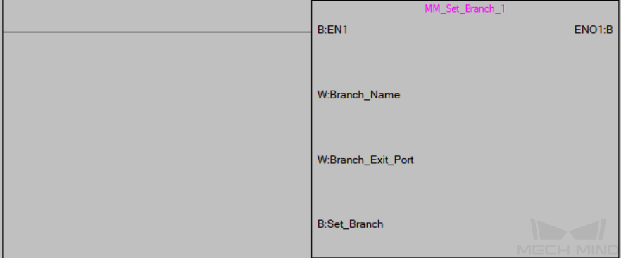
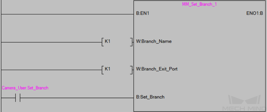
Set the branch parameters in Mech-Viz project. Set the port value of Branch_Name and Branch_Exit_Port to 1 respectively, and the Mech-Viz project will take the exit port 1 for the “Branch by Msg” Step named 1. Select Open Contact in the pop-up window, and enter the global label Camera_User.Set_Branch. Then, click OK to connect the Set_Branch port with the bus line.
-
Set the pose type of the obtained waypoints. Change the value of “Request_Pose_Type” to 1, and Mech-Viz will return data in the format of joint positions (instead of TCP).
The Request_Pose_Type here and Robot_Pose_Type of the MM_Start_Vis and MM_Start_Viz FB all correspond to the Pose_Type variable of the global label MM_Camera. Therefore, if these parameters are set to different values, the programming should ensure that the two values do not take effect at the same time. -
Double-click the blue frame area on the left of EN1 port of MM_Get_VizData FB. Select Close Contact in the pop-up window, and enter the global label Camera_User.Start_Viz. Then click OK to connect the EN1 port with the left bus line.
-
Double-click the blue frame area on the left of Get_VizData port of MM_Get_VizData FB. Select Open Contact in the pop-up window, and enter the global label Camera_User.Get_VizData. Then click OK to connect the Get_VizData port with the left bus line.
-
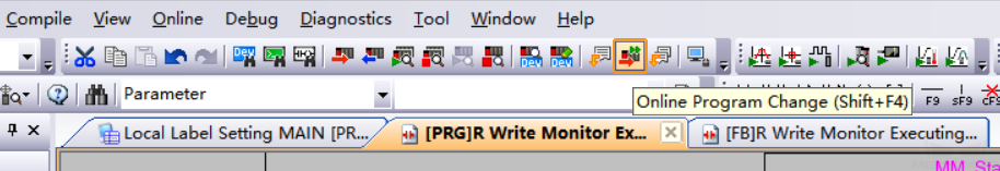
Click the Online Program Change icon in the toolbar.
-
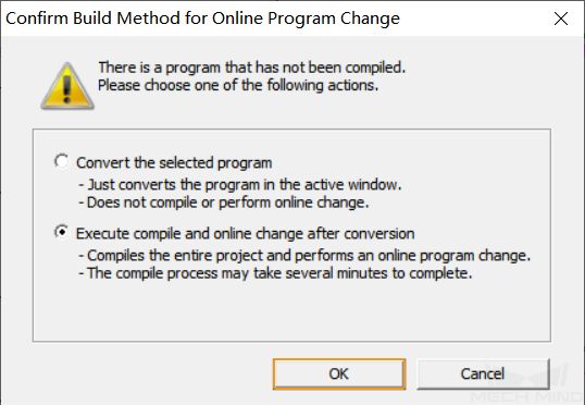
Click OK in the pop-up Confirm Build Method for Online Program Change window.
-
Click Yes in the pop-up window as shown below.
-
Lastly, click OK to complete downloading the program to PLC.
Trigger Mech-Viz Project to Run
-
In the interface of MAIN, right-click the input variable Camera_User.Start_Empty of MM_Start_Empty FB, and select in the context menu. In the pop-up Modify Value window, click ON to clear the previously obtained vision result. Then click OFF to reset the value.
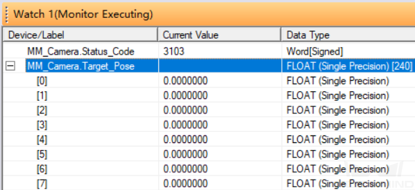
In the Watch1 window, enter the global label MM_Camera.Status_Code. The status code 3103 should be returned, and the variable values of Camera_User.Target Pose, Camera_User.Target Label, and Camera_User.Target Tool ID should be cleared.
-
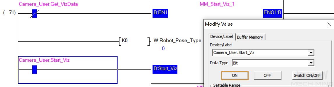
In the interface of MAIN, right-click the input variable Camera_User.Start_Viz of MM_Start_Viz FB. In the pop-up Modify Value window, click ON to trigger the Mech-Viz project to run. Then click OFF to reset the value.
-
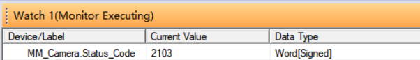
In the Watch1 window, enter the global label MM_Camera.Status_Code. If the project is started successfully, the status code 2103 will be returned. Otherwise, the corresponding error code will be returned. Please refer to Status Codes and Troubleshooting for troubleshooting.
Set Mech-Viz Branch Exit Port
-
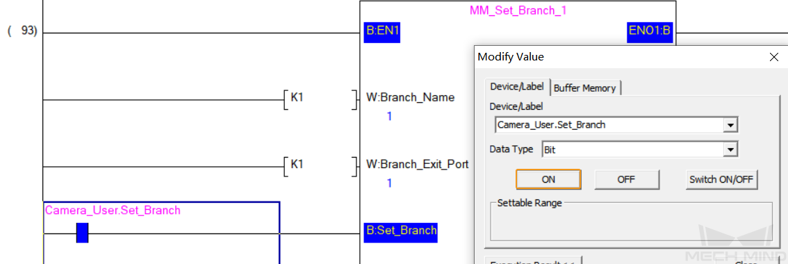
In the interface of MAIN, right-click the input variable Camera_User.Set_Branch of MM_Set_Branch FB. In the pop-up Modify Value window, click ON to choose the Mech-Viz branch. Then click OFF to reset the value.
-
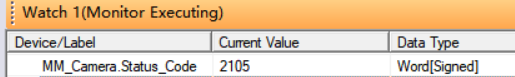
In the Watch1 window, enter the global label MM_Camera.Status_Code. If the branch is set successfully, the status code 2105 will be returned. Otherwise, the corresponding error code will be returned. Please refer to Status Codes and Troubleshooting for troubleshooting.
Obtain Planned Path from Mech-Viz
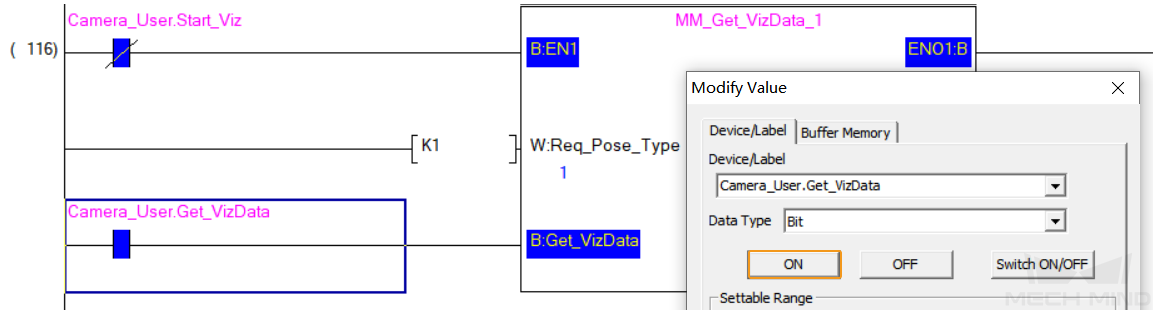
-
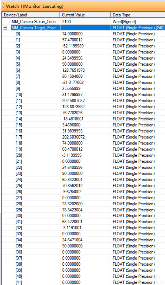
In the interface of MAIN, right-click the input variable Camera_User.Get_VizData of MM_Get_VizData FB. In the pop-up Modify Value window, click ON to obtain the planned path from Mech-Viz. Then click OFF to reset the value.
-
Right-click the blank space, select Register to Watch, and enter the global label MM_Camera.Status_Code. If the planned path are obtained successfully, the status code 2100 will be returned. Otherwise, the corresponding error code will be returned. Please refer to Status Codes and Troubleshooting for troubleshooting. Then enter the global label MM_Camera.Target_Pose, and the JPs of the waypoints in the path planned by Mech-Viz will be returned.