Example Program 1: MM_S1_Vis_Basic
Program Introduction
Description |
The robot triggers the Mech-Vision project to run, and then obtains the vision result for picking and placing the object. |
File path |
You can navigate to the installation directory of Mech-Vision and Mech-Viz and find the file by using the |
Project |
Mech-Vision project |
Prerequisites |
|
| This example program is provided for reference only. Before using the program, please modify the program according to the actual scenario. |
Program Description
This part describes the MM_S1_Vis_Basic example program.
1: !-------------------------------- ;
2: !FUNCTION: trigger Mech-Vision ;
3: !project and get vision result ;
4: !Mech-Mind, 2023-12-25 ;
5: !-------------------------------- ;
6: ;
7: !set current uframe NO. to 0 ;
8: UFRAME_NUM=0 ;
9: !set current tool NO. to 1 ;
10: UTOOL_NUM=1 ;
11: !move to robot home position ;
12:J P[1] 100% FINE ;
13: !initialize communication ;
14: !parameters(initialization is ;
15: !required only once) ;
16: CALL MM_INIT_SKT('8','127.0.0.1',30000,5) ;
17: !move to image-capturing position ;
18:L P[2] 1000mm/sec FINE ;
19: !trigger NO.1 Mech-Vision project ;
20: CALL MM_START_VIS(1,0,2,10,53) ;
21: !check whether vision project has ;
22: !been triggered successfully ;
23: IF (R[53]<>1102),JMP LBL[99] ;
24: !get vision result from NO.1 ;
25: !Mech-Vision project ;
26: CALL MM_GET_VIS(1,51,53) ;
27: !check whether vision result has ;
28: !been got from Mech-Vision ;
29: !successfully ;
30: IF R[53]<>1100,JMP LBL[99] ;
31: !save first vision point data to ;
32: !local variables ;
33: CALL MM_GET_POS(1,60,70,80) ;
34: !move to intermediate waypoint ;
35: !of picking ;
36:J P[3] 50% CNT100 ;
37: !move to approach waypoint ;
38: !of picking ;
39:L PR[60] 1000mm/sec FINE Tool_Offset,PR[1] ;
40: !move to picking waypoint ;
41:L PR[60] 300mm/sec FINE ;
42: !add object grasping logic here, ;
43: !such as "DO[1]=ON" ;
44: PAUSE ;
45: !move to departure waypoint ;
46: !of picking ;
47:L PR[60] 1000mm/sec FINE Tool_Offset,PR[1] ;
48: !move to intermediate waypoint ;
49: !of placing ;
50:J P[4] 50% CNT100 ;
51: !move to approach waypoint ;
52: !of placing ;
53:L P[5] 1000mm/sec FINE Tool_Offset,PR[2] ;
54: !move to placing waypoint ;
55:L P[5] 300mm/sec FINE ;
56: !add object releasing logic here, ;
57: !such as "DO[1]=OFF" ;
58: PAUSE ;
59: !move to departure waypoint ;
60: !of placing ;
61:L P[5] 1000mm/sec FINE Tool_Offset,PR[2] ;
62: !move back to robot home position ;
63:J P[1] 100% FINE ;
64: END ;
65: ;
66: LBL[99:vision error] ;
67: !add error handling logic here ;
68: !according to different ;
69: !error codes ;
70: !e.g.: status=1003 means no ;
71: !point cloud in ROI ;
72: !e.g.: status=1002 means no ;
73: !vision results ;
74: !e.g.: status=3099 means ;
75: !failed to open socket ;
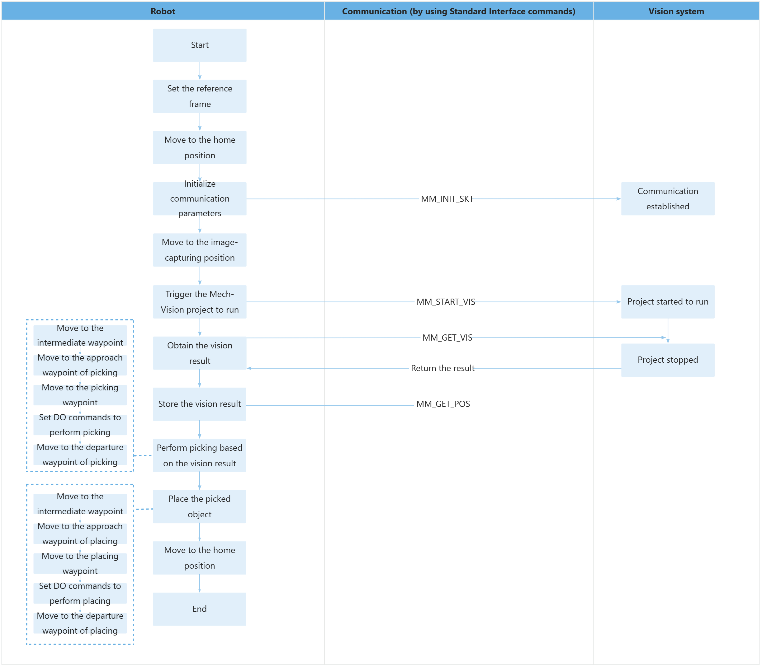
76: PAUSE ;The workflow corresponding to the above example program code is shown in the figure below.
The table below explains the above program. You can click the hyperlink to the command name to view its detailed description.
| Feature | Code and description | ||
|---|---|---|---|
Set the reference frame |
The above two statements set the selected user and tool reference frames. |
||
Move to the home position |
The entire statement indicates that the robot moves to the taught home position by using joint position movement.
|
||
Initialize communication parameters |
The entire statement indicates that the robot establishes the connection with the vision system by specifying the IP address, port number, and timeout period of the communication target (the IPC) through the MM_INIT_SKT command.
|
||
Move to the image-capturing position |
The entire command indicates that the robot moves to the image-capturing position in linear motion, with a velocity of 1000 mm/sec.
|
||
Trigger the Mech-Vision project to run |
The entire statement indicates that the robot triggers the vision system to run the Mech-Vision project with an ID of 1 and expects the Mech-Vision project to return all vision points.
The statement means that when the status code in R[53] is 1102, the robot has successfully obtained all vision result; otherwise, an exception has occurred in the vision system, and the program will jump to LBL[99] and execute the instructions there. The following is the code at LBL[99]. |
||
Obtain the vision result |
The entire statement indicates that the robot obtains the vision result from the Mech-Vision project with an ID of 1.
The statement means that when the status code in R[53] is 1100, the robot has successfully obtained all vision result; otherwise, an exception has occurred in the vision system, and the program will jump to LBL[99] and execute the instructions there. The following is the code at LBL[99]. You can perform the corresponding operation based on the specific error code. In this example program, all error codes are handled in the same way, by stopping the program execution using the PAUSE command. |
||
Store the vision result |
The entire statement stores the TCP, label, and tool ID of the first vision point in the specified registers. |
||
Move to the intermediate waypoint |
The entire statement moves the robot in joint positions to a certain intermediate waypoint between the image-capturing position and the approach waypoint of picking.
|
||
Move to the approach waypoint of picking |
The entire statement directs the robot to move linearly to a position situated above the picking waypoint.
|
||
Move to the picking waypoint |
The robot moves from the approach waypoint of picking to the picking waypoint linearly. |
||
Set DO commands to perform picking |
After the robot moves to the picking waypoint, you can set a DO command (such as “DO[1]=ON”) to control the robot to use the tool to perform picking. Please set DO commands based on the actual situation.
|
||
Move to the departure waypoint of picking |
The robot moves to position above the picking waypoint and reaches the departure waypoint of picking.
|
||
Move to the intermediate waypoint |
The robot moves to a intermediate waypoint between the departure waypoint of picking and the approach waypoint of placing.
|
||
Move the robot to the approach waypoint of placing |
|
||
Move to the placing waypoint |
The robot moves from the approach waypoint of placing to the placing waypoint. |
||
Set DO commands to perform placing |
After the robot moves to the placing waypoint, you can set a DO command (such as “DO[1]=OFF”) to control the robot to use the tool to perform placing. Please set DO commands based on the actual situation.
|
||
Move the robot to the departure waypoint of placing |
The robot moves to a position above the placing waypoint and reaches the departure waypoint of placing.
|
||
Move to the home position |
The robot moves from the departure waypoint of placing to the home position again. |