Example Program 1: MM_S1_Vis_Basic
Program Introduction
Description |
The robot triggers the Mech-Vision project to run, and then obtains the vision result for picking and placing the object. |
File path |
You can navigate to the installation directory of Mech-Vision and Mech-Viz and find the file by using the |
Project |
Mech-Vision project |
Prerequisites |
|
| This example program is provided for reference only. Before using the program, please modify the program according to the actual scenario. |
Program Description
This part describes the MM_S1_Vis_Basic example program.
DEF MM_S1_Vis_Basic ( )
;---------------------------------------------------
; FUNCTION: trigger Mech-Vision project and get
; vision result
; Mech-Mind, 2023-12-25
;---------------------------------------------------
;set current tool no. to 1
BAS(#TOOL,1)
;set current base no. to 0
BAS(#BASE,0)
;move to robot home position
PTP HOME Vel=100 % DEFAULT
;initialize communication parameters (initialization is required only once)
MM_Init_Socket("XML_Kuka_MMIND",873,871,60)
;move to image-capturing position
LIN camera_capture Vel=1 m/s CPDAT1 Tool[1] Base[0]
;trigger NO.1 Mech-Vision project
MM_Start_Vis(1,0,2,init_jps,status)
IF status <> 1102 THEN
;add error handling logic here according to different error codes
MM_LOG("Status ERROR")
HALT
ENDIF
;get vision result from NO.1 Mech-Vision project
MM_Get_VisData(1,pos_num,status)
;check whether vision result has been got from Mech-Vision successfully
IF status<> 1100 THEN
;add error handling logic here according to different error codes
;e.g.: status=1003 means no point cloud in ROI
;e.g.: status=1002 means no vision result
halt
ENDIF
;save first vision point data to local variables
MM_Get_Pose(1,Xpick_point,label,toolid)
;calculate pick approach point based on pick point
tool_offset={X 0,Y 0,Z -100,A 0,B 0,C 0}
Xpick_app=Xpick_point:tool_offset
;move to intermediate waypoint of picking
PTP pick_waypoint CONT Vel=50 % PDAT1 Tool[1] Base[0]
;move to approach waypoint of picking
LIN pick_app Vel=1 m/s CPDAT2 Tool[1] Base[0]
;move to picking waypoint
LIN pick_point Vel=0.3 m/s CPDAT3 Tool[1] Base[0]
;add object grasping logic here, such as "$OUT[1]=TRUE"
halt
;move to departure waypoint of picking
LIN pick_app Vel=1 m/s CPDAT2 Tool[1] Base[0]
;move to intermediate waypoint of placing
PTP drop_waypoint CONT Vel=100 % PDAT2 Tool[1] Base[0]
;move to approach waypoint of placing
LIN drop_app Vel=1 m/s CPDAT4 Tool[1] Base[0]
;move to placing waypoint
LIN drop Vel=0.3 m/s CPDAT5 Tool[1] Base[0]
;add object releasing logic here, such as "$OUT[1]=FALSE"
halt
;move to departure waypoint of placing
LIN drop_app Vel=1 m/s CPDAT4 Tool[1] Base[0]
;move back to robot home position
PTP HOME Vel=100 % DEFAULT
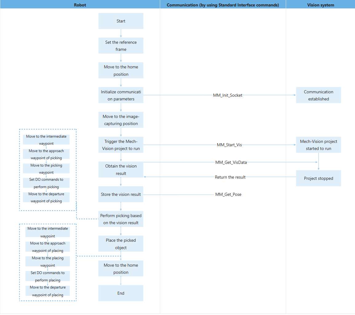
ENDThe workflow corresponding to the above example program code is shown in the figure below.
The table below explains the above program. You can click the hyperlink to the command name to view its detailed description.
| Feature | Code and description | ||
|---|---|---|---|
Set the reference frame |
The above two statements set the current tool and base reference frames. |
||
Move to the home position |
The above statement specifies to move the robot in PTP mode to the taught home position. |
||
Initialize communication parameters |
The MM_Init_Socket command establishes the TCP communication between the robot and the vision system based on the configurations in the XML_Kuka_MMIND.xml file.
|
||
Move to the image-capturing position |
The above statement specifies to move the robot linearly to the taught image-capturing position. |
||
Trigger the Mech-Vision project to run |
The entire statement indicates that the robot triggers the vision system to run the Mech-Vision project with an ID of 1 and expects the Mech-Vision project to return all vision points.
The above statement indicates that when the status code is 1102, the robot successfully triggers the Mech-Vision project to run; otherwise, an exception has occurred in the vision system and the program executes the code between IF and ENDIF. You can perform the corresponding operation based on the specific error code. In this example program, all error codes are handled in the same way, by pausing the program execution using the halt command. |
||
Get the vision result |
The entire statement indicates that the robot obtains the vision result from the Mech-Vision project with an ID of 1.
The above statement indicates that when the status code is 1100, the robot has successfully obtained all vision result; otherwise, an exception has occurred in the vision system and the program executes the code between IF and ENDIF. You can perform the corresponding operation based on the specific error code. In this example program, all error codes are handled in the same way, by pausing the program execution using the halt command. |
||
Store the vision result |
The entire statement stores the TCP, label, and tool ID of the first vision point in the specified variables.
The above two statements calculate the position of the approach waypoint of picking. In the subsequent steps, the robot will reach this position. |
||
Move to the intermediate waypoint |
The robot moves in PTP mode to a intermediate waypoint (pick_waypoint) between the image-capturing point and the approach waypoint of picking.
|
||
Move to the approach waypoint of picking |
The robot moves linearly to a point 100 mm above the picking waypoint (i.e. the approach waypoint of picking). pick_app and Xpick_app indicate the same position.
|
||
Move to the picking waypoint |
The robot moves linearly from the approach waypoint of picking to the picking waypoint. pick_point and Xpick_point indicate the same position. |
||
Set DOs to perform picking |
After the robot moves to the picking waypoint, you can set a DO (such as “$OUT[1]=TRUE”) to control the robot to use the tool to perform picking. Please set DOs based on the actual situation.
|
||
Move to the departure waypoint of picking |
The robot moves to 100 mm above the picking waypoint and reaches the departure waypoint of picking. pick_app and Xpick_app indicate the same position.
|
||
Move to the intermediate waypoint |
The robot moves to a intermediate waypoint (drop_waypoint) between the departure waypoint of picking and the approach waypoint of placing.
|
||
Move the robot to the approach waypoint of placing |
The robot moves from the intermediate waypoint to the approach waypoint of placing (drop_app).
|
||
Move to the placing waypoint |
The robot moves from the approach waypoint of placing to the placing waypoint (drop).
|
||
Set DOs to perform placing |
After the robot moves to the placing waypoint, you can set a DO (such as “$OUT[1]=FALSE”) to control the robot to use the tool to perform placing. Please set DOs based on the actual situation.
|
||
Move the robot to the departure waypoint of placing |
The robot moves from the placing waypoint to the departure waypoint of placing (drop_app).
|
||
Move to the home position |
The robot moves from the departure waypoint of placing to the home waypoint again.
|