Establish the communication between PLC and the vision system |
-
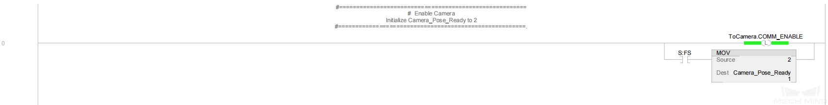
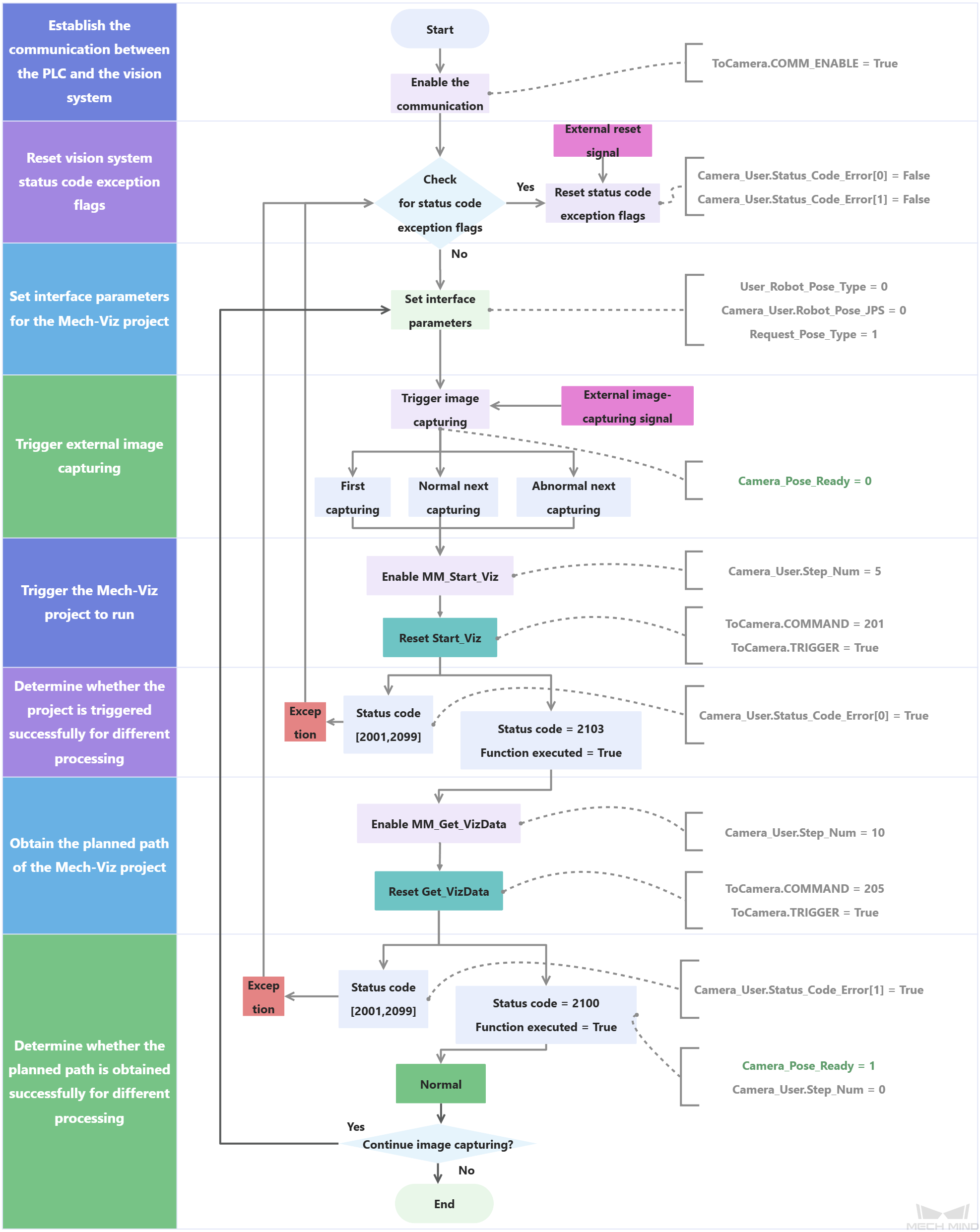
ToCamera.COMM_ENABLE: Specify whether to enable the triggering of the signal. True indicates that the trigger signal will work, and the vision system will receive the command sent by the PLC. False indicates that the vision system will ignore the command sent by the PLC.
-
S:FS: Conducted only during the first scan cycle.
-
MOV: Set Camera_Pose_Ready to 2.
-
Camera_Pose_Ready: Indicate whether the PLC obtained the planned path.
-
0: The PLC did not obtain the planned path when the camera was about to capture images or had already captured images, or when Mech-Viz was calculating the planned path.
-
1: The camera captured images, and the PLC obtained the planned path.
-
2: The camera was ready to start capturing images for the first time, and the PLC did not obtain the planned path.
Therefore, Rung 0 indicates that ToCamera.COMM_ENABLE is reset, and Camera_Pose_Ready is set to 2 in the first scan cycle.
|
Reset vision system status code exception flags |
-
Camera_User.Status_Code_Error[0]: A vision system status code exception flag. True indicates that the Mech-Viz project was not successfully run, i.e., an exception occurred in the vision system.
-
Camera_User.Status_Code_Error[1]: A vision system status code exception flag. True indicates that the Mech-Viz project failed to output the planned path, i.e., an exception occurred in the vision system.
-
External_Reset_Camera_Error: An external reset signal. When an exception occurs in the vision system and the signal changes from False to True, reset the succeeding Camera_User.Status_Code_Error[0] and Camera_User.Status_Code_Error[1].
Therefore, Rung 1 indicates that when External_Reset_Camera_Error is triggered, reset Camera_User.Status_Code_Error[0] and Camera_User.Status_Code_Error[1].
|
Set interface parameters for the Mech-Viz project |
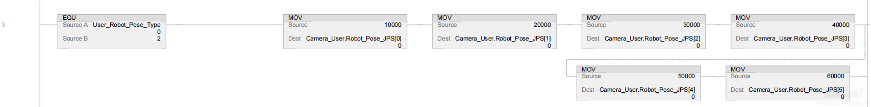
Therefore, Rung 2 indicates that User_Robot_Pose_Type is set to 2.
-
Camera_User.Robot_Pose_JPS[0] to [5]: Six pieces of joint position data of the robot. When User_Robot_Pose_Type is set to 2, the joint position data is custom joint position data defined at the robot side. The values of Camera_User.Robot_Pose_JPS[0] to [5] should be consistent with the value of the Robot_Pose_JPS parameter of the MM_Start_Viz command. In this example, the joint positions of robot J1 to J6 are set to 10000, 20000, 30000, 40000, 50000, and 60000 in sequence. You can modify the value as needed and add the robot flange pose data (that is, the value of the Robot_Pose_TCP parameter in the MM_Start_Viz command).
Therefore, Rung 3 indicates that if User_Robot_Pose_Type is set to 2, Camera_User.Robot_Pose_JPS[0] to Camera_User.Robot_Pose_JPS[5] will be set to 10000, 20000, 30000, 40000, 50000, and 60000.
|
Trigger external image capturing |
-
External_Photo_Signal: The external signal to trigger image capturing when a rising edge occurs.
-
Camera_User.Set_Edge[0]: Obtain the rising edge for External_Photo_Signal by running the ONS command.
-
FromCamera.STATUS_CODE: The vision system status code. 2103 indicates that the PLC successfully triggered the Mech-Viz project to run. 2100 indicates that the PLC successfully obtained the planned path from Mech-Viz.
-
FromCamera.COMMAND_COMPLETE: Indicate whether the vision system completed executing the command sent by the PLC. True indicates that the command was executed, while False indicates that the command was not executed.
-
Camera_User.Start_Viz: The flag that triggers the Mech-Viz project to run when the rising edge occurs.
-
Camera_User.Get_VizData: The flag that triggers the retrieval of Mech-Viz planned path when the rising edge occurs.
Therefore, Rung 4 indicates that the external signal to trigger image capturing when a rising edge occurs is retrieved, and then the following three image capturing operations are performed, as shown in the figure.
-
An image is captured for the first time. FromCamera.STATUS_CODE is set to 0, and Camera_Pose_Ready is set to 2.
-
An image is captured normally at the next time. FromCamera.STATUS_CODE is set to 2100, and FromCamera.COMMAND_COMPLETE is set to True.
-
An error is reported when an image is captured at the next time. FromCamera.STATUS_CODE is not equal to 2100, and both Camera_User.Status_Code_Error[0] and Camera_User.Status_Code_Error[1] are set to False.
Finally, Camera_User.Step_Num is set to 5, Camera_Pose_Ready is set to 0, and Camera_User.Start_Viz and Camera_User.Get_VizData are reset.
|
Trigger the Mech-Viz project to run and determine whether the project is triggered successfully for different processing |
|
|
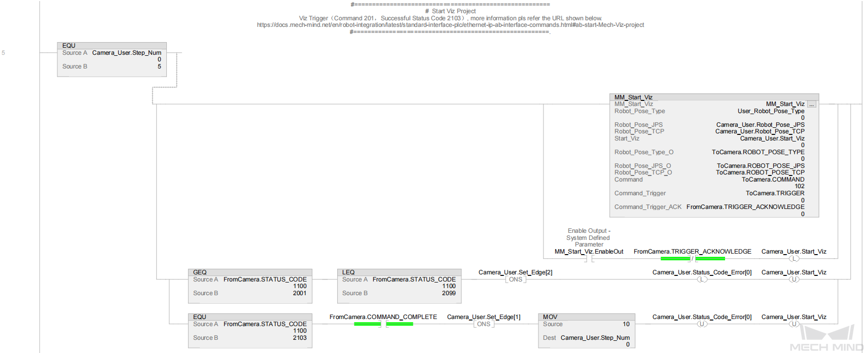
For more information about input and output parameters in MM_Start_Viz, see MM_Start_Viz.
|
Rung 5 indicates that if Camera_User.Step_Num is set to 5, the following operations are performed.
-
Enable MM_Start_Viz.
-
When MM_Start_Viz.EnableOut is set to True and FromCamera.TRIGGER_ACKNOWLEDGE is set to False, reset Camera_User.Start_Viz and the PLC triggers the Mech-Viz project to run.
-
If the value of FromCamera.STATUS_CODE is greater than or equal to 2001 and less than or equal to 2099, an exception occurs in the vision system. In this case, after receiving the rising edge for the logic output by using the ONS command, set Camera_User.Status_Code_Error[0] and reset Camera_User.Start_Viz. For information about the cause of a specific status code, see Standard Interface status codes and error codes.
-
If the value of FromCamera.STATUS_CODE is 2103 and FromCamera.COMMAND_COMPLETE is set to True, the vision system has successfully executed the command sent by the PLC. In this case, call the ONS command to retrieve the rising edge for the logical output, assign a value of 10 to Camera_User.Step_Num, and then reset Camera_User.Status_Code_Error[0] and Camera_User.Start_Viz.
|
Obtain the planned path of the Mech-Viz project and determine whether the planned path is obtained successfully for different processing |
|
|
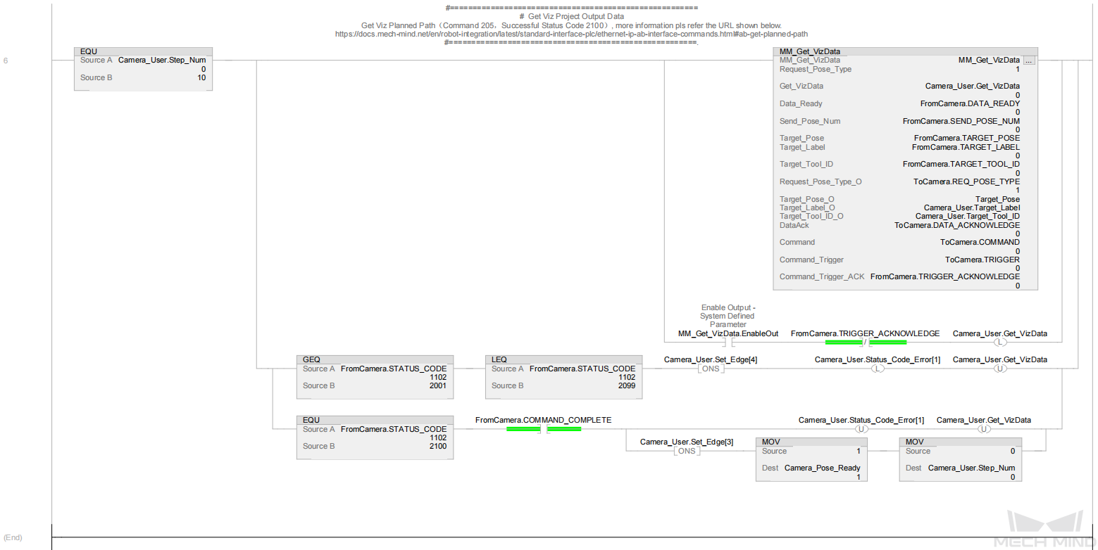
For more information about input and output parameters in MM_Get_VizData, see MM_Get_VizData.
|
Rung 6 indicates that if Camera_User.Step_Num is set to 10, the following operations are performed.
-
Enable MM_Get_VizData.
-
When MM_Get_VizData.EnableOut is set to True and FromCamera.TRIGGER_ACKNOWLEDGE is set to False, reset Camera_User.Get_VizData and the PLC starts to obtain planned path output by the Mech-Viz project.
-
If the value of FromCamera.STATUS_CODE is greater than or equal to 2001 and less than or equal to 2099, an exception occurs in the vision system. In this case, after retrieving the rising edge for the logic output by using the ONS command, set Camera_User.Status_Code_Error[1] and reset Camera_User.Get_VizData. For information about the cause of a specific status code, see Standard Interface status codes and error codes.
-
If FromCamera.STATUS_CODE is set to 2100 and FromCamera.COMMAND_COMPLETE is set to True, the vision system has successfully executed the command sent by the PLC. In this case, reset Camera_User.Status_Code_Error[1] and Camera_User.Get_VizData. Retrieve the rising edge on the logical output by using the ONS command when FromCamera.STATUS_CODE equals 2100 and FromCamera.COMMAND_COMPLETE equals True and set Camera_Pose_Ready to 1 and Camera_User.Step_Num to 0. This means that the PLC has obtained the planned path from Mech-Viz and can forward the planned path to the robot.
|