Master-Control Communication Setup (xCore)
This guide shows you how to load the Master-Control program to a ROKAE robot(xCore system), and set up the Master-Control communication between the robot and the Mech-Mind Vision System.
| In this section, you will load the robot Master-Control program to the robot system to establish the Master-Control communication between the vision system and the robot. |
Preparation
Set up the Network Connection
On the ROKAE robot base or controller cabinet, an Ethernet port is preset as the debug port, and its IP address is fixed at 192.168.0.160. This address is the same on all robots and should not be modified unless necessary. Therefore, the user only needs to connect the robot to the industrial PC with an Ethernet cable and then change the IPC IP address; the detailed steps are as follows.
-
Use the Ethernet cable to connect the network ports of the IPC and the robot controller. The debug Ethernet ports for each robot are shown in the table below.
Robot model Debug Ethernet port (192.168.0.160) Illustration ER/ER PRO
J2 Ethernet port

CR
J1 Ethernet port
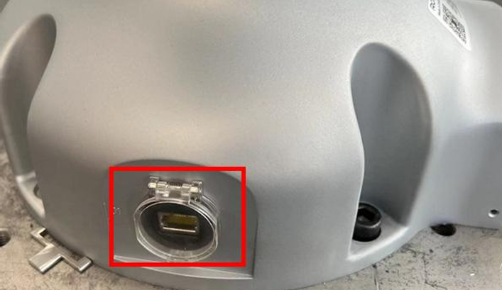
CR-C
Controller cabinet Ethernet port
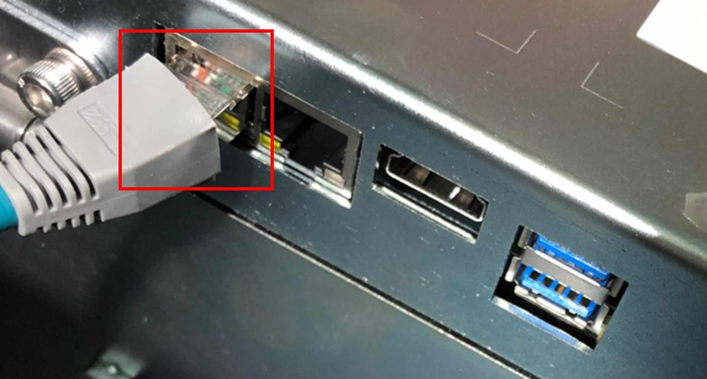
SR
J2 Ethernet port

SR-C
LAN2 Ethernet port

XBC5/XBC5E
Debug Ethernet port

XBC5M
LAN2 Ethernet port

For models not listed above, contact the robot manufacturer or test each Ethernet port’s IP address to locate the port with IP address 192.168.0.160. -
Open the command prompt window on the IPC and enter the command ping 192.168.0.160 to verify the communication connection status between the robot and the IPC.
If the connection fails, check the network port of the robot and the IP address of the IPC to ensure correct configuration for both devices. -
On the IPC, install and launch the Robot Assist. Navigate to , enter the IP address 192.168.0.160, then click Connect. If a pop-up indicates that the current robot model is not supported, complete the update as prompted by the software.
-
Robot Assist is the host software for ROKAE robots and runs on PCs and on devices such as xPad2. Connect the device running the Robot Assist software and the robot to the same local area network (LAN). You can establish a connection to the robot by using robot discovery or by manually entering the controller’s service address.
-
In this document, the Robot Assist control software is installed on the same IPC as the vision system.
-
Check Controller Compatibility
In the Robot Assist interface, go to to view the xCore controller version.
|
Load the Program Files
In Manual mode, load the Master-Control program as follows.
-
In the Robot Assist interface, go to . Under User Groups, set User Level to Administrator, enter the password 12345(default initial password), then click .
If the user switches to Administrator and performs no operation for 10 minutes, the system will automatically switch from Administrator to Operator. -
In the interface shown, go to .
-
In the interface shown, click Open, select the xcore_control.zip file located at the software installation path
Mech-Vision and Mech-Viz …/Robot_Server/Robot_FullControl/rokae, click Open, keep the other options at their default values, and finally click Finish. After a successful import, a notification will appear in the bottom-right corner of the interface. -
After a successful import, in the interface shown, select the xcore_control project and click Reload. In the pop-up dialog, click Confirm.
Configure External Communication
-
In the Robot Assist interface, go to .
-
In the communication settings, set Type to Client, Suffix to \r, IP to the IPC IP address, and Port to 8081, then click OK.
-
In the top toolbar, set the External Communication switch to Enabled.
You can configure the communication settings only when the External Communication switch is Disabled.
Test Master-Control Communication
Create a Mech-Viz Project
-
Open Mech-Viz, press Ctrl + N on the keyboard to create a new project. In the following interface, click Load online robot list. Select the robot model corresponding to your real robot brand and model on the interface as shown below.

-
Press Ctrl + S and create or select a folder to save the project.
-
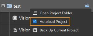
Right-click the project name in the left panel in Mech-Viz and select Autoload Project.
Connect the Robot
-
Select Master-Control Robot on the toolbar of Mech-Viz.
-
Input 192.168.0.160 in Robot IP address and select Connect the robot.

Mech-Viz will wait for the master-control program to run before establishing the connection. By default, the waiting time is 120s.

With the following steps, you can load and run the master-control program. Note that the operation should be completed in 120 seconds. Otherwise, you’ll need to select Connect the robot in Mech-Viz again. -
In the Robot Assist interface, go to ; the
xcore_control/task0/mainprogram will be displayed. -
In the bottom bar, adjust the program speed as needed, then switch from Manual mode to Automatic mode, and finally power on the robot motors. The final state is as shown below.
-
Click the green arrow in front of main; the program pointer will point to the main function.
-
In the right sidebar, click the Run button (if there is no Run button, click Next Page).
-
If Mech-Viz successfully connects the real robot, the current status will change to Connected. Meanwhile, the icon in the toolbar will turn from blue to green.

If the connection fails, please double-check the IP address of the IPC, clear any robot alarms, and rerun the Master-Control program.
Move robot
-
In the toolbar of Mech-Viz, change the “Vel.” (velocity) and “Acc.” (acceleration) parameters to 5%.

-
Click Sync Robot in the toolbar, and you can synchronize the poses of the simulated robot in the 3D simulation space with the poses of the real robot. Then click Sync Robot again to unselect it.

-
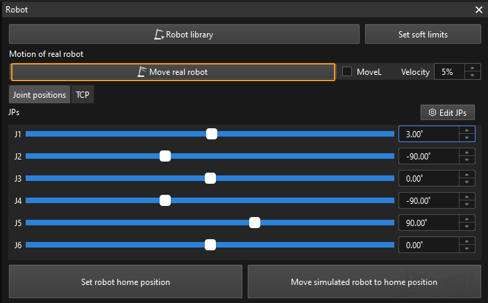
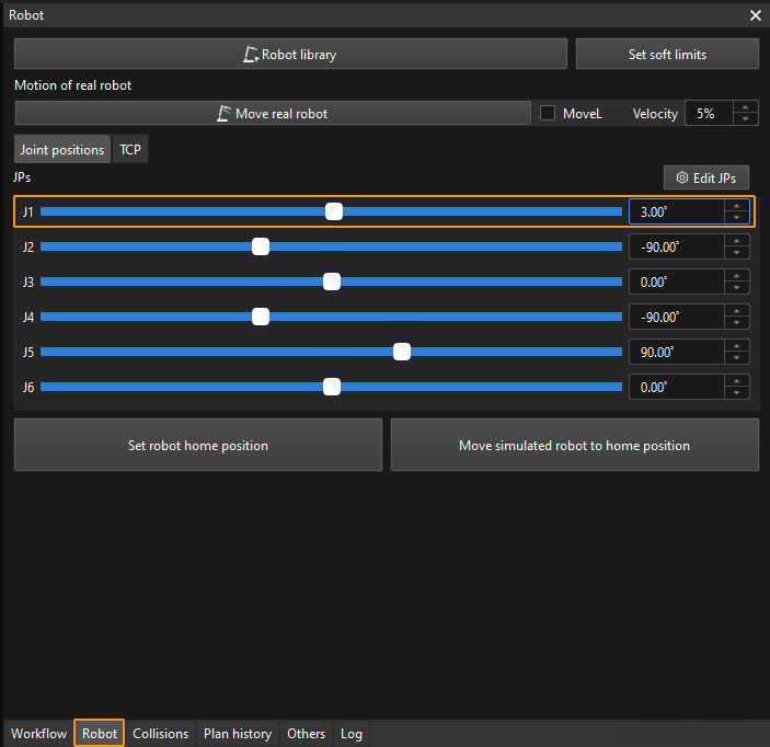
In the Robot tab, slightly adjust the value of “J1”, for example, from 0˚ to 3˚. This operation will move the simulated robot.
-
Click Move real robot and check if the real robot has moved. If the real robot has reached the JPs set for the simulated robot, the Master-Control communication is working.
When moving the robot, please ensure the safety of personnel. In the case of an emergency, press the emergency stop button on the button box immediately!