Example Program 22: MM_S22_Vis_As_Uframe
Program Introduction
Description |
The robot triggers the Mech-Vision project to run, obtains the vision result, sets the vision result as the user frame, and then performs picking and placing. |
File Name |
You can navigate to the installation directory of Mech-Vision and Mech-Viz and find the file by using the |
Project |
Mech-Vision project |
Prerequisites |
|
| This example program is provided for reference only. Before using the program, please modify the program according to the actual scenario. |
Program Description
This part describes the MM_S22_Vis_As_Uframe example program.
| The only difference between the MM_S22_Vis_As_Uframe example program and the MM_S1_Vis_Basic example program is that the vision result will be used as the user frame (for example target object frame) for picking. As such, only the modification is described in the following part. For information about the parts of MM_S22_Vis_As_Uframe that are consistent with those of MM_S1_Vis_Basic, see Example Program 1: MM_S1_Vis_Basic. |
   1:  !-------------------------------- ;
   2:  !FUNCTION: trigger Mech-Vision ;
   3:  !project and get vision result ;
   4:  !as the uframe 7 ;
   5:  !Mech-Mind, 2026-1-23 ;
   6:  !-------------------------------- ;
   7:   ;
   8:  !set current uframe NO. to 0 ;
   9:  UFRAME_NUM=0 ;
  10:  !set current tool NO. to 1 ;
  11:  UTOOL_NUM=1 ;
  12:  !move to robot home position ;
  13:J P[1] 100% FINE    ;
  14:  !initialize communication ;
  15:  !parameters(initialization is ;
  16:  !required only once) ;
  17:  CALL MM_INIT_SKT('8','192.168.1.20',30000,5) ;
  18:  !move to image-capturing position ;
  19:L P[2] 1000mm/sec FINE    ;
  20:  !trigger NO.1 Mech-Vision project ;
  21:  CALL MM_START_VIS(1,0,2,10,53) ;
  22:  !check whether vision project has ;
  23:  !been triggered successfully ;
  24:  IF (R[53]<>1102),JMP LBL[99] ;
  25:  !get vision result from NO.1 ;
  26:  !Mech-Vision project ;
  27:  CALL MM_GET_VIS(1,51,53) ;
  28:  !check whether vision result has ;
  29:  !been got from Mech-Vision ;
  30:  !successfully ;
  31:  IF (R[53]<>1100),JMP LBL[99] ;
  32:  !save first vision point data to ;
  33:  !local variables ;
  34:  CALL MM_GET_POS(1,60,70,80) ;
  35:  !move to intermediate waypoint ;
  36:  !of picking ;
  37:J P[3] 50% CNT100    ;
  38:   ;
  39:  !set the uframe for camera ;
  40:  UFRAME[7]=PR[60] ;
  41:  UFRAME_NUM=7 ;
  42:   ;
  43:  !move to approach waypoint ;
  44:  !of picking ;
  45:L P[6] 1000mm/sec FINE Tool_Offset,PR[1]    ;
  46:  !move to picking waypoint ;
  47:L P[6] 300mm/sec FINE    ;
  48:  !add object grasping logic here, ;
  49:  !such as "DO[1]=ON" ;
  50:  PAUSE ;
  51:  !move to departure waypoint ;
  52:  !of picking ;
  53:L P[6] 1000mm/sec FINE Tool_Offset,PR[1]    ;
  54:   ;
  55:  !change the uframe ;
  56:  UFRAME_NUM=0 ;
  57:   ;
  58:  !move to intermediate waypoint ;
  59:  !of placing ;
  60:J P[4] 50% CNT100    ;
  61:  !move to approach waypoint ;
  62:  !of placing ;
  63:L P[5] 1000mm/sec FINE Tool_Offset,PR[2]    ;
  64:  !move to placing waypoint ;
  65:L P[5] 300mm/sec FINE    ;
  66:  !add object releasing logic here, ;
  67:  !such as "DO[1]=OFF" ;
  68:  PAUSE ;
  69:  !move to departure waypoint ;
  70:  !of placing ;
  71:L P[5] 1000mm/sec FINE Tool_Offset,PR[2]    ;
  72:  !move back to robot home position ;
  73:J P[1] 100% FINE    ;
  74:  END ;
  75:   ;
  76:  LBL[99:handling error] ;
  77:  !add error handling logic here ;
  78:  !according to different ;
  79:  !error codes ;
  80:  !e.g.: mm_status=1003 means no ;
  81:  !point cloud in ROI ;
  82:  !e.g.: mm_status=1002 means no ;
  83:  !vision results ;
  84:  !e.g.: mm_status=3099 means ;
  85:  !failed to open socket ;
  86:  PAUSE ;
The workflow corresponding to the above example program code is shown in the figure below.
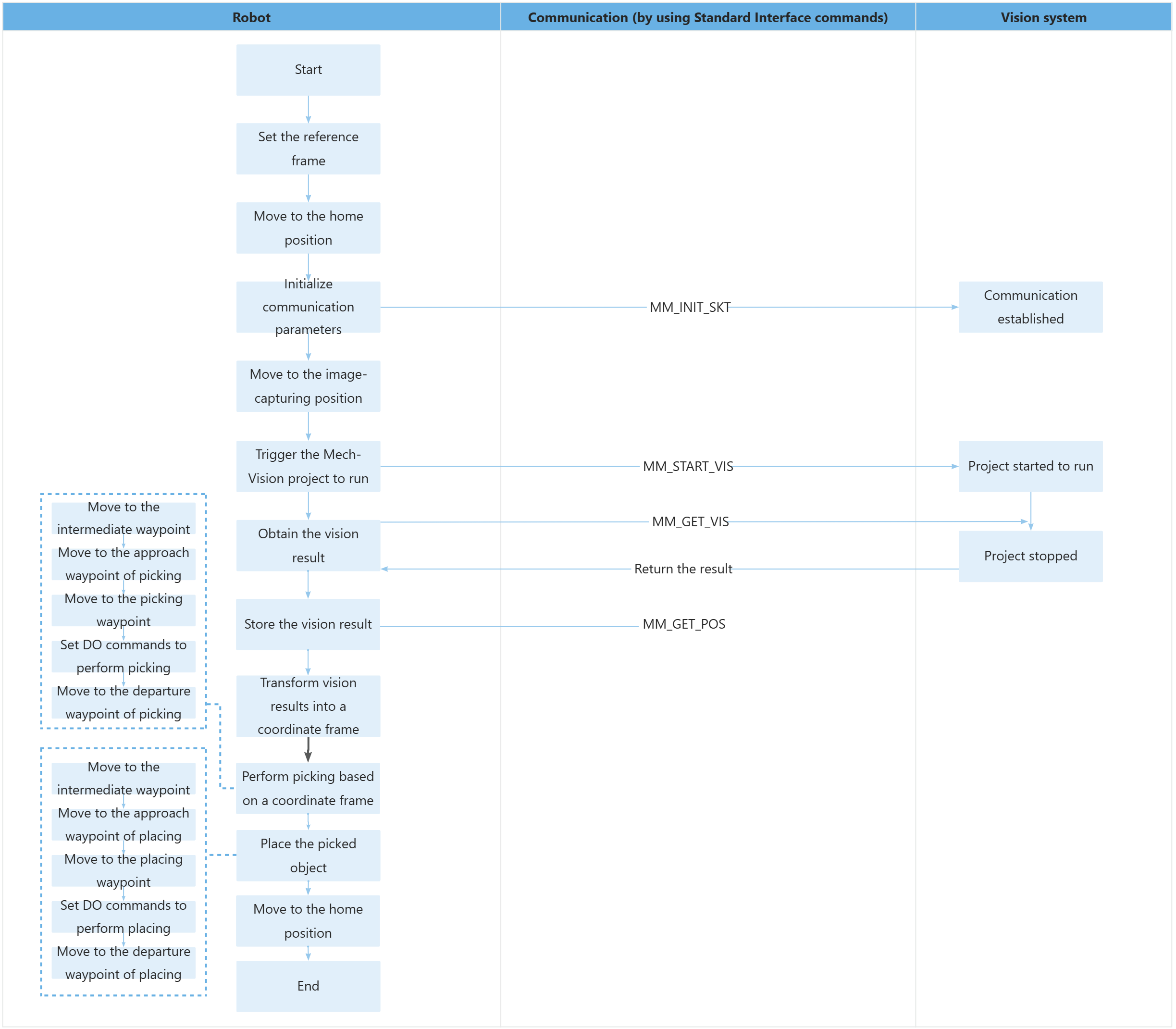
The table below describes the feature of using for loops to obtain all planned paths and perform picking and placing. You can click the hyperlink to the command name to view its detailed description.
| Feature | Code and description |
|---|---|
Set up the vision coordinate system |
|
Picking and Placing Process |
The code indicates that the robot first switches to the vision-matched user frame to perform the pick, then switches back to the default frame to execute the placement, and finally returns to the home position to end the program. UFRAME[7] = PR[60] assigns the pose data obtained from vision recognition to user coordinate system 7. UFRAME_NUM = 7 activates this vision coordinate system, so that subsequent picking motions are executed based on the vision‑recognized workpiece position. After picking is completed, UFRAME_NUM = 0 switches back to the robot base coordinate system, ensuring that the placing motion is executed based on the preset reference position. Tool_Offset, PR[1] and Tool_Offset, PR[2] are the tool offset parameters for the picking and placing phases respectively. They are used to control the safe offset of the robot end-effector when approaching or leaving the workpiece to avoid collisions. |