Adapter Generator Guide
This guide introduces the Adapter generator and shows how to quickly generate an Adapter program using the Adapter generator. In the text below, “Adapter” is used as a short form for “Adapter program”.
Introduction
Adapter Generator is a tool for conveniently generating an Adapter program. Users may generate an Adapter program simply by configuring parameters on a graphical interface. Users may also customize the program files to implement more advanced features that go beyond the capabilities of the Standard Interface communication.
The Adapter program is a Python program that facilitates the communication between an external device (such as an industrial robot, host computer, or PLC) and Mech-Vision / Mech-Viz. It utilizes communication protocols supported by Python to establish the connection.
The relationship between the Adapter Generator and the Adapter program is shown in the image below.
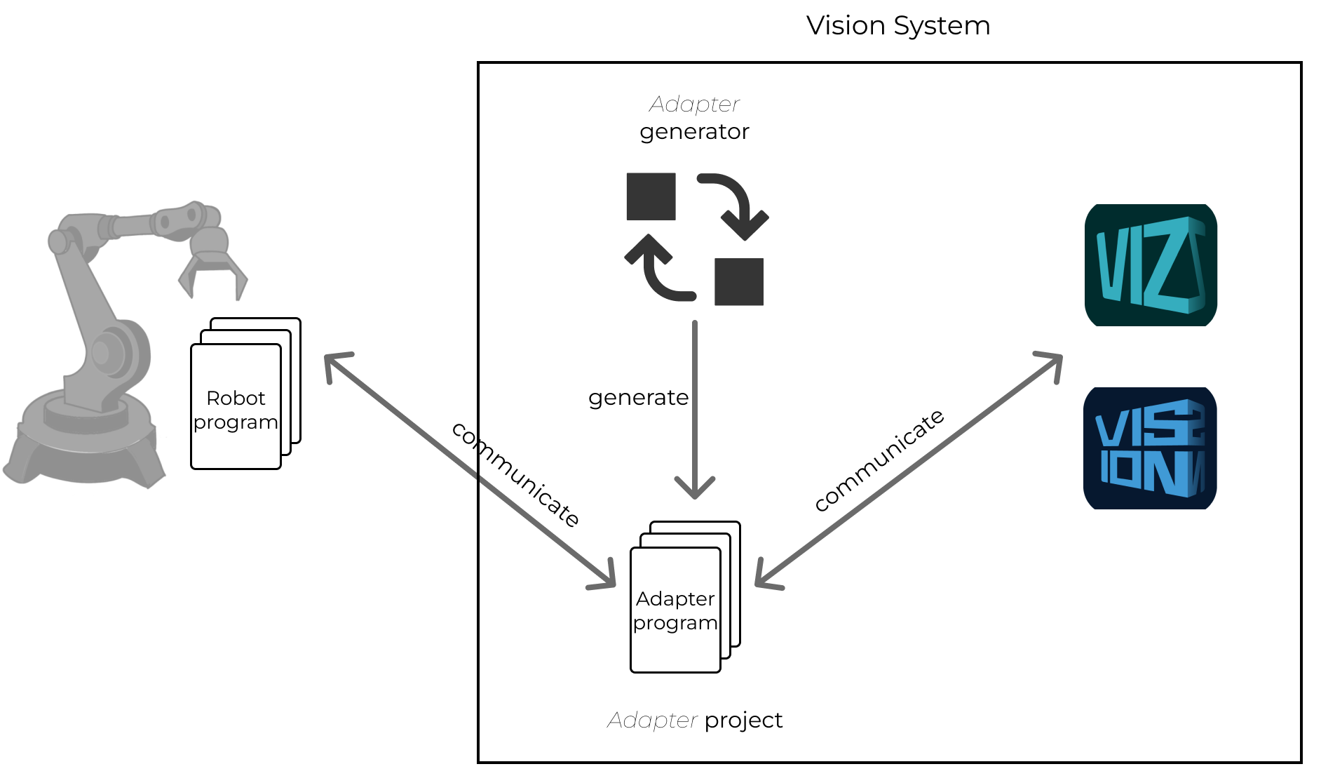
The main function of the Adapter Generator is to configure the commands used for communication between the robot program and the Adapter program. The commands that trigger Mech-Vision / Mech-Viz to capture images and set Step parameters for Mech-Vision / Mech-Viz are listed in the configuring workflow of the Adapter Generator. Users may configure one or more of these commands according to the communication object and your practical requirements. The workflow of setting up the Adapter Generator is show in the image below.

The table below explains how to select the communication object for the Adapter program.
Communicate with |
Description |
Applicable scenarios |
Mech-Vision |
Obtain vision results or planned paths from Mech-Vision. |
Simple path planning projects or projects that only involve sending vision results. |
Mech-Viz |
Mech-Viz plans the path by calling the vision service corresponding to a Mech-Vision project. Meanwhile, before the Mech-Viz project calls the vision service, Mech-Vision Step parameters do not need to be set or can be set in the parameter recipe. |
More complicated path planning projects. |
Mech-Vision & Mech-Viz |
Mech-Viz plans the path and one of the following situations exists:
|
Users may consider to select this communication object when the two options above cannot meet project requirements. |
Generate Adapter Program Using Adapter Generator
This section introduces how to rapidly generate an Adapter program using the Adapter Generator.
| Before starting, please make sure that you have set up and opened a Mech-Vision solution and a Mech-Viz project (if any). |
Open Adapter Generator
On the menu bar of Mech-Vision, click , and the Adapter Generator window will pop up.
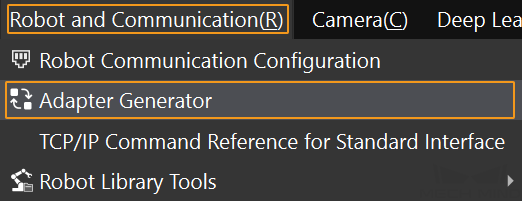
|
Configure “Basic settings”
-
On the Basic settings tab page, configure Adapter project name, Communicate with, Communication protocol and Communication format.
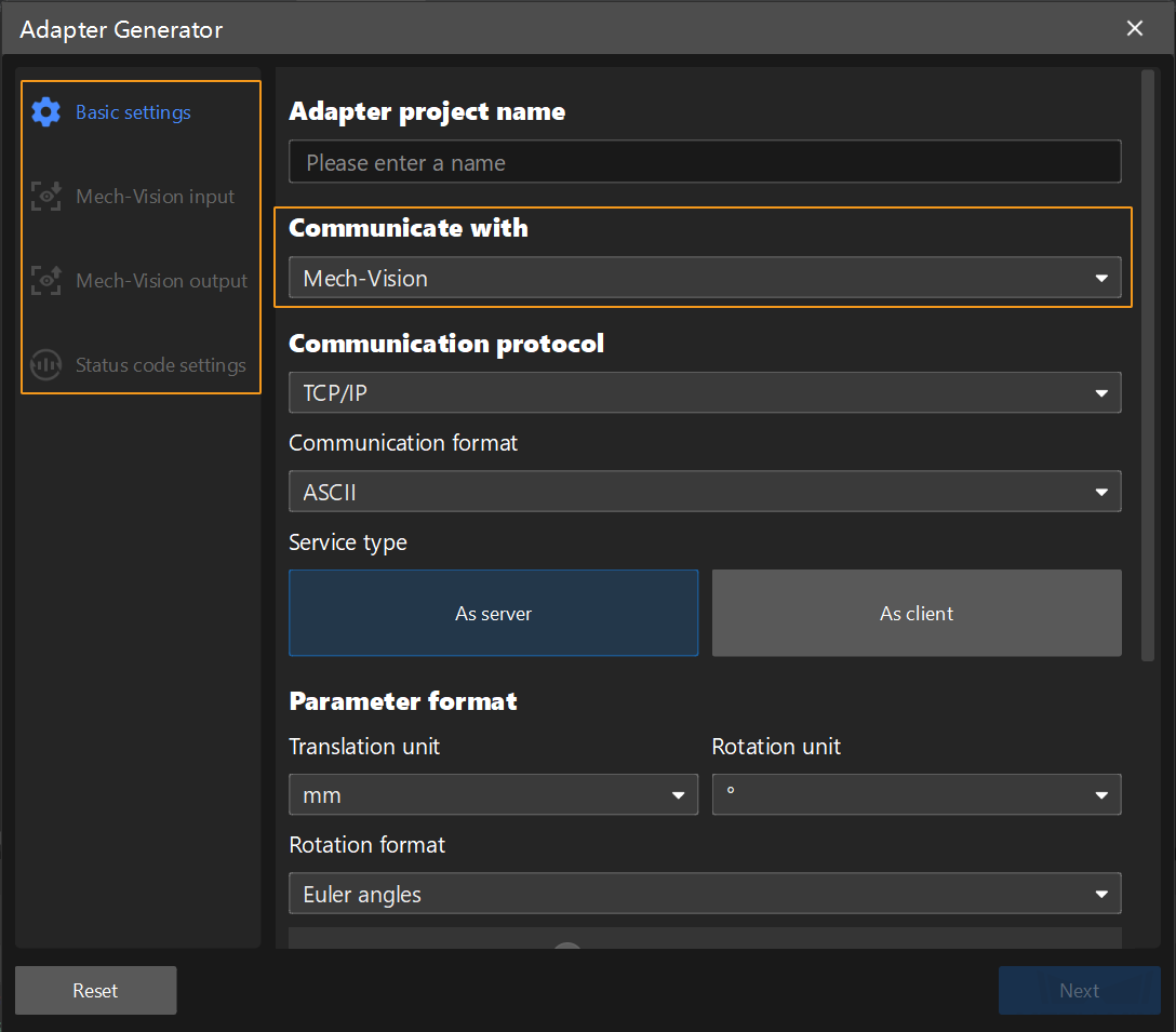
The configuration workflow varies depending on the value of Communicate with. In other words, the left panel displays different configuration options based on the value of Communicate with. For example, when the value Mech-Vision is selected for “Communicate with”, you will only need to configure Basic settings, Mech-Vision input, Mech-Vision output and Status code settings. Configure Basic settings according to the instructions in the table below.
Configuration entry Description Adapter project name
This parameter specifies the Adapter project name. The project name is a string of letters, numbers or underscores and cannot start with a number.
Communicate with
Mech-Vision
Mech-Vision input and output need to be configured.
Mech-Viz
Mech-Viz input and output need to be configured.
Mech-Vision & Mech-Viz
Both Mech-Vision input and output and Mech-Viz input and output need to be configured.
Communication protocol
TCP/IP
Communication format
This parameter specifies the string format for data transmission. Currently, only the ASCII format is supported.
Service type
This parameter specifies whether the Adapter project is used as a server or client in the TCP/IP communication. By default, the project is used as a server.
Parameter format
Translation unit
mm (millimeter, default) or m (meter)
Rotation unit
° (degree, default) or rad (radian)
Rotation format
Euler angles
The Euler angles format is frequently used. Select the value of Euler angles convention based on the robot model.
-
ABB/EPSON/ESTUN/KUKA/NACHI: Z-Y'-X''(ZYX_ROTATED)
-
AUBO/DENSO/DOBOT/DELTA/EFORT/ELITE/FANUC/FLEXIV/FR/HANS/HYUNDAI/JAKA/MELFA/ROKAE/SIASUN/STEP/TM/YASKAWA: X-Y-Z(XYZ_STATIC)
-
COMAU/DOOSAN/KAWASAKI/QJAR: Z-Y'-Z''(ZYZ_ROTATED)
-
STAUBLI/TURIN: X-Y'-Z''(XYZ_ROTATED)
-
UR: ur_rot
Quaternion
When this parameter value is selected, all poses in the input and output data will be transmitted in the format of quaternion.
Other data format
Decimal place of floating point number
This parameter specifies the decimal place of the floating point number. The value ranges from 1 to 20. The default value is 4.
String delimiter
This parameter specifies the string delimiter. Common string delimiters include the English comma, semicolon and space. By default, the string delimiter is the English comma.
These three configuration entries appear only when the communication protocol is TCP/IP and the communication format is ASCII.
String terminator
This parameter specifies the string terminator of commands. Common string terminators are \n, \r and \r\n. By default, the terminator is \r.
Add start and end character
This option specifies the start and end character of a command. After selecting this option, users should enter a start character and an end character. By default, both are space. For example, when the start and end character of the command “p,1\r” are respectively < and >, then the full form of the command is “<p,1>\r”.
-
-
After finishing the configuration above, click Next. You will be directed to the command configuration interface based on the setting of “Communicate with”.
Configure “Mech-Vision input”
Set the command formats sent by the robot or host computer to Mech-Vision on the Mech-Vision input tab page. Configuration entries include Triggering command, Set Mech-Vision Step parameters and Get robot name from Mech-Vision.
Configure Triggering Command
-
Configure the command that triggers Mech-Vision to capture images.
This command is mainly used to trigger the Mech-Vision project to run. This command can also fulfill the following functions when corresponding parameters are configured.
-
If the Mech-Vision project has parameter recipes, this command can be used to switch the parameter recipe.
-
If the camera is mounted in eye in hand mode, or the Mech-Vision project has a “Path Planning” Step, this command can be used to input the robot capturing pose to the Mech-Vision project.
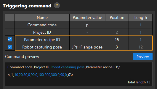
Configure Triggering command according to explanations in the table below.
Name: The names of parameters in the command.
Parameter value: The value of a parameter.
Position: The position of a parameter in the command. The position order starts with 1. Two positions are separated by a comma.
Length: The count of fields within a parameter value. (A field is the data between two adjacent string delimiters.
Relationship between Position and Length: The position of a parameter equals the position of the previous parameter plus the length of the previous parameter.
Name Parameter value Position Length Command code
The code to trigger the Mech-Vision project to run. The default value is p. The value can be modified.
1 (fixed value)
1 (fixed value)
Project ID
The ID of the Mech-Vision project, a positive integer.
2 (fixed value)
1 (fixed value)
Parameter recipe ID (optional)
The ID of the parameter recipe in the Mech-Vision project, a positive integer.
User-defined value
1 (fixed value)
Robot capturing pose (optional)
If the camera mounting mode is eye in hand, this command inputs the robot’s pose at the time of image capturing to the Mech-Vision project. The parameter value can be set to “JPs” or “JPs+Flange pose”.
User-defined value
-
If you have selected “Euler angles” for the “Rotation format” parameter:
-
When the parameter value is “JPs”, the length is fixed to 6.
-
When the parameter value is “JPs+Flange pose”, the length is fixed to 12.
-
-
If you have selected “Quaternion” for the “Rotation format” parameter:
-
When the parameter value is “JPs”, the length is fixed to 6.
-
When the parameter value is “JPs+Flange pose”, the length is fixed to 13.
-
-
-
If a value in the Parameter value, Position and Length columns is not gray, users may click it to modify the value as needed.
-
The command code should be unique among different commands.
-
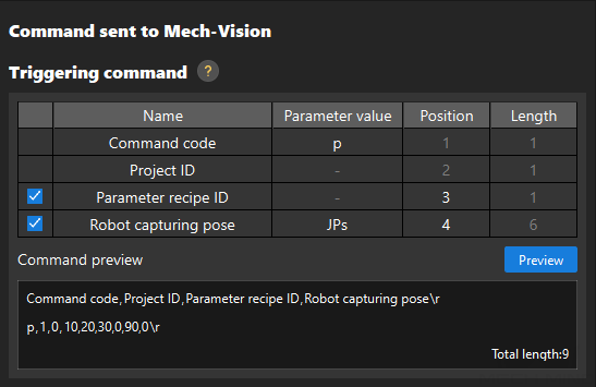
Make sure that the fields occupied by different parameters do not overlap. For example, in the image below, the position and length of “robot capturing pose” are 3 and 12 respectively. If the position and length of “parameter recipe ID” are respectively 4 and 1, then the second field of “robot capturing pose” will overlap with the position of “parameter recipe ID”. If the position of “parameter recipe ID” is equal to or greater than 15, the “parameter recipe ID” and “robot capturing pose” will not overlap.
-
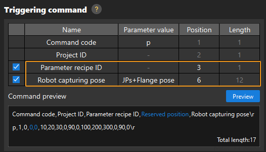
There might be empty fields between parameter values. In preview, the empty field is described as the reserved position and filled in with 0s. For example, if the position and length of “parameter recipe ID” are respectively 3 and 1; and the position and length of “robot capturing pose” are respectively 6 and 12, position 4 and 5 are empty fields and will be filled in with 0s. If the position of “robot capturing pose” is changed to 4, there will be no empty field between this parameter value and that of “parameter recipe ID”. It is recommended to assign a proper value to “position” to avoid empty fields.
-
-
After completing the above configurations, click Preview to generate a command example.
In the Command preview text box, users may hover the cursor over the field name to see the corresponding data, which will be highlighted.
Set Mech-Vision Step Parameters (Optional)
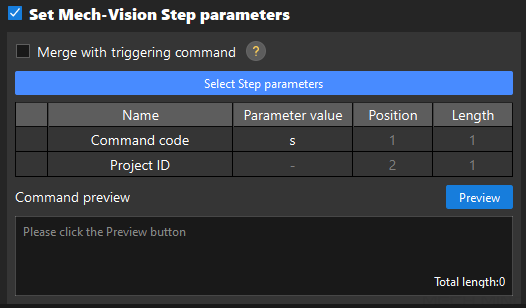
If a Step parameter cannot be predefined in the parameter recipe or needs to be configured based on external information, select Set Mech-Vision Step parameters to configure the command that sets Step parameter values.
-
Decide whether to select Merge with triggering command.
“Merging with triggering command” means to add the Step parameters set for Mech-Vision to the triggering command. Set Mech-Vision Step parameters command can be either merged with the command that triggers Mech-Vision to capture images or used as an individual command. In the latter case, this command should be called before the triggering command.
Determine whether to select Merge with triggering command according to the explanation table below and then complete corresponding operations.
-
If you have selected Mech-Vision & Mech-Viz for “Communicate with” on the Basic settings tab page and need to set Mech-Vision Step parameters, do not select Merge with triggering command. Configure the command that sets Mech-Vision Step parameters according to the information in the table below, and continue to execute the next step.
Name
Parameter value
Position
Length
Command code
The code to set Mech-Vision Step parameters. The default value is s. The value can be modified.
1 (fixed value)
1 (fixed value)
Project ID
The ID of the Mech-Vision project, a positive integer.
2 (fixed value)
1 (fixed value)
Parameter recipe ID (optional)
The ID of the parameter recipe in the Mech-Vision project, a positive integer.
User-defined value
1 (fixed value)
-
If you have selected Mech-Vision for “Communicate with” on the Basic settings tab page and need to set Mech-Vision Step parameters, you can choose whether to select Merge with triggering command or not. If Merge with triggering command is selected, the parameter names and values in the table above will be merged with those configured for the triggering command.
-
-
Select Step parameters.
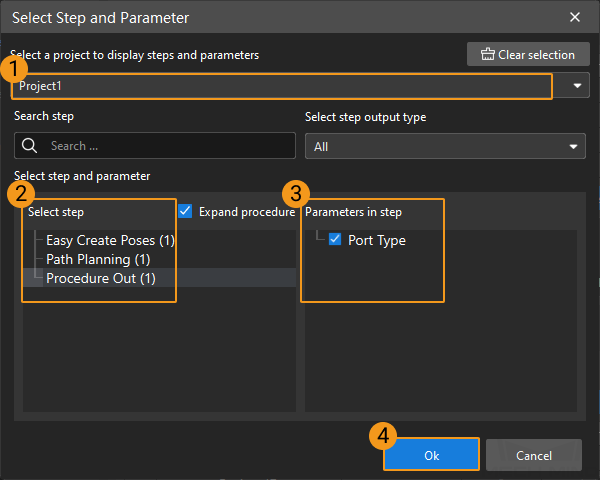
Click Select Step parameters, and select Steps and parameters in the pop-up window following the instructions below.
-
Select a project of the solution. The corresponding Steps and parameter names will show up.
-
Click the Step to be configured on the Select Step list.
-
Select the needed parameter names on the Parameters in step list.
-
Click Ok.
-
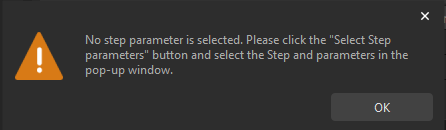
If Set Mech-Vision Step parameters is selected, you must select at least one Step parameter. Otherwise, the warning below will prompt.
-
Users may select multiple Steps and parameters.
-
If the Boolean data type is adopted by Step parameter values, then 1 and 0 respectively represent true and false.
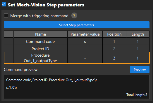
Take the configuration above as an example. After clicking Ok, the “Set Mech-Vision Step parameters” area is as follows.
-
-
Make sure that the fields occupied by different parameters do not overlap.
-
There might be empty fields between parameter values. It is recommended to assign a proper value to “position” to avoid empty fields.
-
-
After completing the above configurations, click Preview to generate a command example.
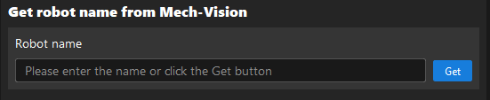
Get Robot Name from Mech-Vision
-
Click Get, the robot model selected in Robot Communication Configuration will be displayed in the text box.
The obtained robot name is used to register a robot service. The robot name displayed here varies according to the configuration in the Robot Communication Configuration interface.
Robot selection Robot name Listed robot
Robot brand and model
Custom robot
RobotType1
Not use robot
no robot found
-
After completing the configuration above, click Next to enter the Mech-Vision output configuration tab page.
Configure “Mech-Vision output”
On the Mech-Vision output tab page, set the command formats returned by Mech-Vision to the robot or host computer. Configuration entries include Pose data, Object label and Other output.
-
Determine which configuration entries you need to set based on the port types of the “Output” Step of the Mech-Vision project.
Port type of “Output” Step Port name Configuration entry Applicable scenarios Predefined (vision result)
poses
Pose data (vision point data)
Obtain the pose of the target object.
Predefined (vision result)
poses, labels
Pose data (vision point data), Object label
Obtain the pose and label of the target object.
Predefined (robot path)
moves
Pose data (robot path)
Plan the path for the robot to move to the target object.
Custom
User defined
Other output
Obtain custom port outputs, for example, OCR text, VIN codes, measurements, etc.
-
Set the configuration entries following the description below.
Configuration entry
Description
Pose data
Vision point data (Select this option when the Mech-Vision project does not have a “Path Planning” Step.)
Quantity
Value options: One, Fixed (input by users) or All
-
One: Adapter only returns the first vision point out of the total N vision points output by Mech-Vision.
-
Fixed (for example, the value is M): Adapter returns the first M vision points out of the total N vision points output by Mech-Vision.
-
All: Adapter returns all of the total N vision points output by Mech-Vision.
Number of poses sent
The data returned by Mech-Vision includes the number of poses sent this time. In the output data, the position of the pose count parameter is before the pose parameter(s).
Convert object pose to robot pose
Automatically flip the pose in the recognition result from Mech-Vision around the X-axis by 180° to make the Z-axis point downwards, which enables the robot move directly to that pose for object picking.
Robot path (Select this option when the Mech-Vision project has a “Path Planning” Step.)
Pose type
Value: JPs or TCP
Number of poses sent
The data returned by Mech-Vision includes the number of poses sent this time. In the output data, the position of the pose count parameter is before the pose parameter(s).
Index of the vision point in the path
The position of the waypoint corresponding to the “Vision Move” Step of the Path Planning tool in the entire planned path.
Motion type MOVEJ / MOVEL
The motion type of waypoint. 1 represents MOVEJ, and 2 represents MOVEL.
Object label
Output of the labels port of the “Output” Step.
Other output (Click the “+” icon to configure parameters for multiple ports)
Port name
The name of the custom port of the “Output” Step.
Data type
Value: stringlist or numberlist
-
Ensure that the data list length of the custom output matches that of the output of the labels or poses port. Otherwise, error may occur when Other output data is transmitted.
-
In the scenario where Vision point data is selected for “Pose data”, if “Quaternion” is selected for “Rotation format” on the Basic settings tab page, each pose in the output data occupies 7 fields.
-
In the scenario where Robot path is selected for “Pose data” and “Quaternion” is selected for “Rotation format” on the Basic settings tab page, if “TCP” is selected for “Pose type”, each pose in the output data occupies 7 fields; and if “JPs” is selected for “Pose type”, each pose in the output data occupies 6 fields.
-
When none of the configuration entries is selected, user cannot move to the next configuration tab.
-
-
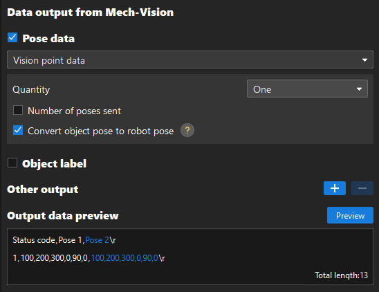
After completing the above configurations, click Preview to generate a command example. If the data preview meets expectation, click Next to enter the next configuration tab.
Configure “Mech-Viz input”
Configure the command formats by the robot or host computer to Mech-Viz on the Mech-Viz input tab page. Configuration entries include Triggering command, Set Mech-Viz Step parameters and Get robot name from Mech-Viz.
Configure Triggering Command
-
Configure the command that triggers Mech-Viz to capture images.
This command is mainly used to trigger the Mech-Viz project to run. This command can also fulfill the following functions when corresponding parameters are configured.
-
If the Mech-Vision project corresponding to the vision service of the Mech-Viz project has parameter recipes, this command can be used to switch the parameter recipe.
-
If the Mech-Viz project has a “Branch by Msg” Step, this command can be used to set the exit port.
-
If the camera mounting mode is eye in hand or if the starting point of the path planning in Mech-Viz is a teaching point, this command can be used to send the pose at the time of image capturing or the teaching point to the Mech-Viz project.
Configure Triggering command according to explanations in the table below.
Name: The names of parameters in the command.
Parameter value: The value of a parameter.
Position: The position of a parameter in the command. The position order starts with 1. Two positions are separated by a comma.
Length: The count of fields within a parameter value. (A field is the data between two adjacent string delimiters.
Relationship between Position and Length: The position of a parameter equals the position of the previous parameter plus the length of the previous parameter.
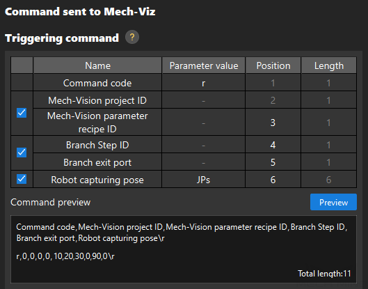
Name Parameter value Position Length Command code
The code to trigger the Mech-Viz project to run. The default value is r. The value can be modified.
1 (fixed value)
1 (fixed value)
Mech-Vision project ID (optional)
The ID of the Mech-Vision project, a positive integer.
2 (fixed value)
1 (fixed value)
Mech-Vision parameter recipe ID (optional)
The ID of the parameter recipe in the Mech-Vision project, a positive integer.
User-defined value
1 (fixed value)
Branch Step ID (optional)
The Step ID of the “Branch by Msg” Step. Applicable when the Mech-Viz project has only one “Branch by Msg” Step.
User-defined value
1 (fixed value)
Branch exit port (optional)
The exit port of the “Branch by Msg” Step. For example, if the parameter value is 0, the “Branch by Msg” Step will take port 0 as the exit.
User-defined value
1 (fixed value)
Robot capturing pose (optional)
If the camera mounting mode is eye in hand, this command inputs the robot’s pose at the time of image capturing to the Mech-Viz project. Value: JPs or JPs+Flange pose
User-defined value
-
If you have selected “Euler angles” for the “Rotation format” parameter:
-
When the parameter value is “JPs”, the length is fixed to 6.
-
When the parameter value is “JPs+Flange pose”, the length is fixed to 12.
-
-
If you have selected “Quaternion” for the “Rotation format” parameter:
-
When the parameter value is “JPs”, the length is fixed to 6.
-
When the parameter value is “JPs+Flange pose”, the length is fixed to 13.
-
-
If a value in the Parameter value, Position and Length columns is not gray, users may click it to modify the value as needed.
-
The command code should be unique among different commands.
-
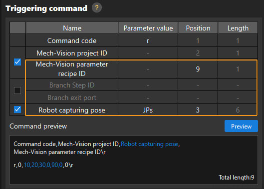
Make sure that the fields occupied by different parameters do not overlap. For example, in the image below, the position and length of “robot capturing pose” are 3 and 6 respectively. If the position and length of “parameter recipe ID” are respectively 4 and 1, then the second field of “robot capturing pose” will overlap with the position of “parameter recipe ID”. If the position of “Parameter recipe ID” is equal to or greater than 9, the “parameter recipe ID” and “robot capturing pose” will not overlap.
-
There might be empty fields between parameter values. In preview, the empty field is described as the reserved position and filled in with 0s. For example, if the position and length of “parameter recipe ID” are respectively 3 and 1; and the position and length of “robot capturing pose” are respectively 6 and 6, position 4 and 5 are empty fields and will be filled in with 0s. If the position of “robot capturing pose” is changed to 4, there will be no empty field between this parameter value and that of “parameter recipe ID”. It is recommended to assign a proper value to “position” to avoid empty fields.

-
If the Mech-Viz project has more than one “Branch by Msg” Step, you can reserve positions for the branch Step ID and branch exit port for the convenience of further development of the Adapter program.

-
-
After completing the above configurations, click Preview to generate a command example.
In the Command preview text box, users may hover the cursor over the field name to see the corresponding data, which will be highlighted.
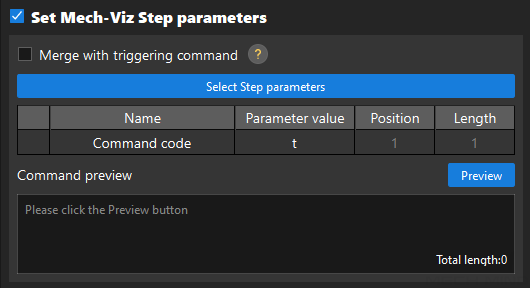
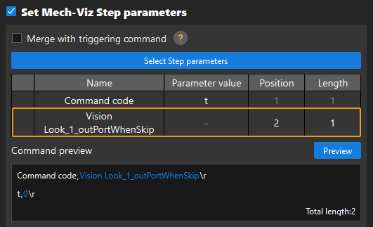
Set Mech-Viz Step Parameters (Optional)
If you need to set Step parameters for Mech-Viz, select Set Mech-Viz Step parameters to configure the command that sets Step parameter values.
-
Decide whether to select Merge with triggering command.
“Merging with triggering command” means to add the Step parameters set for Mech-Viz to the triggering command. Set Mech-Viz Step parameters command can be either merged with the command that triggers Mech-Viz to capture images or used as an individual command. In the latter case, this command should be called before the triggering command.
-
If Merge with triggering command is not selected, configure the command that sets Mech-Viz Step parameters according to the descriptions in the table below, and then execute the second step.
Name
Parameter value
Position
Length
Command code
The code to set Mech-Viz Step parameters. The default value is t. The value can be modified.
1 (fixed value)
1 (fixed value)
-
If Merge with triggering command is selected, the parameter names and values in the table above will be merged with those configured for the triggering command.
-
-
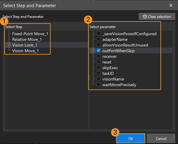
Select Step parameters.
Click Select Step parameters, and select Steps and parameters in the pop-up window following the instructions below.
-
Click the Step to be configured on the Select Step list.
-
Select the needed parameters on the Select parameter list.
-
Click Ok.
-
If Set Mech-Viz Step parameters is selected, you must select at least one Step parameter. Otherwise, the warning below will prompt.
-
Users may select multiple Steps and parameters.
-
If the Boolean data type is adopted by Step parameter values, then 1 and 0 respectively represent true and false.
Take the configuration above as an example. After clicking Ok, the “Set Mech-Viz Step parameters” area is as follows.
-
-
Make sure that the fields occupied by different parameters do not overlap.
-
There might be empty fields between parameter values. It is recommended to assign a proper value to “position” to avoid empty fields.
-
-
After completing the above configurations, click Preview to generate a command example.
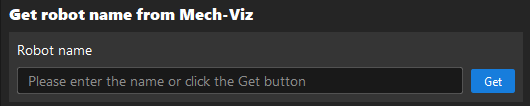
Get Robot Name from Mech-Viz
| Before starting, make sure that the Mech-Viz project is set to autoload. Right-click the project name on the left panel in Mech-Viz and select Autoload Project. |
-
Click Get, and the robot name text box will display the robot model name used by the Mech-Viz project.
-
If the robot name obtained from Mech-Viz is different from the robot name obtained from Mech-Vision, modify the robot name in the Mech-Vision or Mech-Viz projects to ensure agreement.
-
After completing the configuration above, click Next to enter the Mech-Viz output configuration tab page.
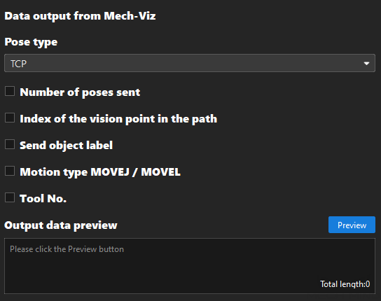
Configure “Mech-Viz output”
On the Mech-Viz output tab page, set the command formats returned by Mech-Viz to the robot or host computer. Configuration entries include Pose type, Number of poses sent, Index of the vision point in the path, Send object label and Motion type MOVEJ/MOVEL, and Tool No..
-
Set the configuration entries following the description below.
Configuration entry
Description
Pose type
Value options: JPs or TCP. The default value is TCP.
Number of poses sent
The data returned by Mech-Viz includes the number of poses sent this time. In the output data, the position of the pose count parameter is before the pose parameter(s).
Index of the vision point in the path
The position of waypoint corresponding to the “Vision Move” Step of the Mech-Viz project in the entire planned path.
Send object label
When this option is selected, Mech-Viz will forward the data output by the labels port in Mech-Vision.
Motion type MOVEJ / MOVEL
The motion type of waypoint. 1 represents MOVEJ, and 2 represents MOVEL.
Tool No.
The ID of the tool used by the robot at the waypoint.
In the scenario where “Quaternion” is selected for “Rotation format” on Basic settings tab page, if “TCP” is selected for “Pose type”, each pose in the output data will occupy 7 fields; and if “JPs” is selected for “Pose type”, each pose in the output data will occupy 6 fields.
-
After completing the above configurations, click Preview to generate a command example. If the data preview meets expectation, click Next to enter the next configuration tab.
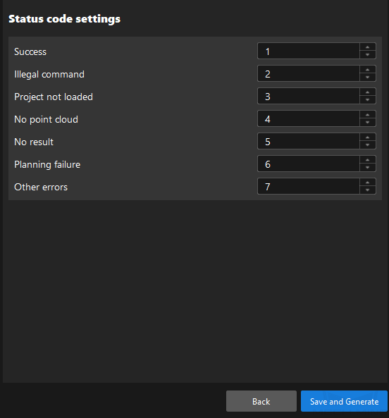
Configure “Status code settings”
-
Configure status codes for different command processing outcomes on the Status code settings tab page.
By default, the Adapter Generator supports 7 status codes. Users may increase or decrease status codes according to needs.
-
Decrease status codes: Assign the same status codes for different situations. For example, users may set the status codes of both “Illegal command” and “Project not loaded” to 2.
-
Increase status codes: Users may modify the Adapter program file to increase status codes. For details, refer to the paragraphs about further development.
-
-
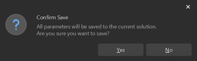
Click Save and Generate after finishing the above configuration. If the following window pops up, the configuration is proper. Click Yes to save all configurations.
Deploy Adapter Program
After configurating the Adapter Generator, users may deploy the program in the project following the steps below.
-
Click Robot Communication Configuration on the toolbar of Mech-Vision.
-
Complete the following settings in the Robot Communication Configuration window.
-
Select a robot model, and click Next.
-
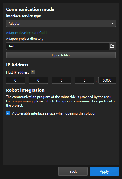
Select Adapter for Interface service type.
-
Click
 in the text box of Adapter project directory. Select an Adapter project file in the pop-up file browser.
 -
(Optional) Select Auto enable interface service when opening the solution.
-
Click the Apply button.
-
-
Make sure the Interface Service is started: The “Robot Communication Configuration” switch on the toolbar of Mech-Vision is flipped and turned to blue.

Now, you have finished creating an Adapter project.
Further Explanations
After you completed the configurations above, the generated Adapter program folder will be saved in the communication folder within the solution folder directory. The name of the Adapter program folder will match the Adapter project name defined in the Adapter Generator. The structure of the communication folder is as follows.
communication
 ├─adapter_generator_config.json (This file contains the configurations set in the Adapter Generator.)
 │
 └─XX (This folder contains the following files. “XX” represents the Adapter project name.)
    ├─XX_adapter.py (This is the Adapter program file generated on the basis of the parameters configured in the Adapter generator.)
    ├─XX_widget.py (This file defines interface elements for the graphical interface. By default, the Widget program is disabled.)
├─__init__.py (This file defines which sub-packages and modules are accessible when the package is imported. User can use this file to enable or disable the Adapter and Widget programs.)|
If you need enable the Widget program, uncomment the line below in the __init__.py file. |
In addition, users may further develop the generated Adapter program to realize more advanced features. For example, you may add the code below to the XX_adapter.py file to set the status code of TIMEOUT to 8.
status_code_dict = {ms.SUCCESS: 1, ms.INVALID_COMMAND: 2, ms.PROJECT_NOT_LOADED: 3,
                    ms.NO_POINT_CLOUD: 4, ms.NO_RESULT: 5, ms.PLAN_FAILED: 6,
                    ms.OTHER_ERROR: 7, ms.TIMEOUT: 8}
Add the code below to raise the TIMEOUT error.
raise AdapterError(ms.TIMEOUT)For details on Adapter programming, refer to the documents below: