Standard Interface Commands
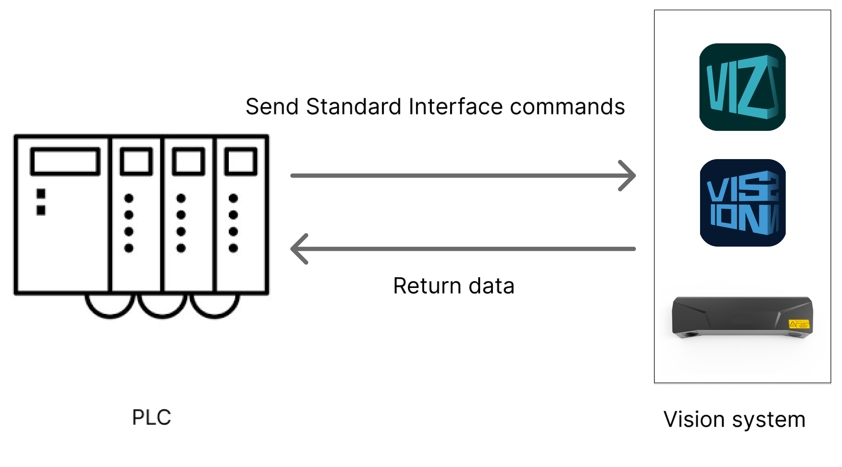
This document describes the standard interface commands for Snap7 communication between a Siemens SIMATIC S7 PLC and Mech-Mind Vision System by using the TIA Portal software. The PLC (the client) sends commands to Mech-Mind Vision System (the server), and Mech-Mind Vision System returns the processed data to the PLC.
Command Overview
Commands related to Mech-Vision |
Commands related to Mech-Viz |
|
Switch Mech-Vision Parameter Recipe Get Planned Path in Mech-Vision |
Precautions
-
Unit of data:
-
The unit of joint positions is degree (°).
-
A robot’s flange pose or TCP consists of the position and pose. The position is represented in XYZ coordinates and is measured in millimeters (mm); the pose is represented in Euler angles and is measured in degrees (°).
-
-
Vision point and waypoint:
-
Vision point: An object recognized by Mech-Vision. A vision point has information including the object pose, label, velocity, dimensions, and custom data.
-
Waypoint: Each point that the robot reaches when moving along the planned path. A waypoint has information including the robot pose, label, motion type, and velocity. Waypoints can be divided into two categories:
-
Vision Move waypoint: Waypoint corresponding to the Vision Move Step.
-
Non-Vision Move waypoints, which refer to the waypoints corresponding to Move-type Steps other than the Vision Move Step.
-
-
Run Mech-Vision Project
Description
This command triggers the Mech-Vision project to run. When the Mech-Vision project is running, the vision system triggers the camera to capture images and then process the returned images with algorithms to produce a series of vision points or waypoints.
|
Calling Sequence
-
You should set Step parameters before starting a Mech-Vision project. Therefore, call Switch Mech-Vision Parameter Recipe or Input Object Dimensions to Mech-Vision Project before calling Run Mech-Vision Project.
-
Vision system gets vision points and waypoints only after a Mech-Vision project runs. Therefore, call Run Mech-Vision Project before calling Get Vision Result or Get Planned Path in Mech-Vision.
Modules
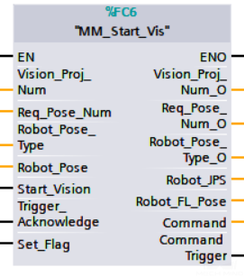
Input Parameters
Vision_Proj_Num
This parameter specifies the Mech-Vision project ID. The data type is INT. You can view the project ID of a Mech-Vision project in the Project List section of Mech-Vision. The project ID is the number before the project name.
Req_Pose_Num
This parameter specifies the number of vision points or waypoints expected to be returned by the Mech-Vision project. The data type is INT. Valid values: 0 to the largest positive integer.
| If the Mech-Vision project has a Path Planning Step, this parameter indicates the expected number of waypoints. Otherwise, it indicates the expected number of vision points. |
-
0: Obtain all vision points or waypoints from the Mech-Vision project.
-
A positive integer: Obtain the specific number of vision points or waypoints from the Mech-Vision project.
-
If the total amount of vision points or waypoints output by the Mech-Vision project is smaller than the parameter value, this command will obtain the number of all vision points or waypoints.
-
If the total amount of vision points or waypoints output by the Mech-Vision project is larger than or equal to the parameter value, this command will obtain the number of vision points or waypoints as specified by this parameter.
-
|
Vision points or waypoints will not be returned after Run Mech-Vision Project is called. To obtain vision points, call Get Vision Result. To obtain waypoints, call Get Planned Path in Mech-Vision. |
Robot_Pose_Type
This parameter specifies the pose type of the real robot to send to the Mech-Vision project. The data type is INT. Valid values: 0, 1, 2, and 3. The following table describes the details.
Robot_Pose
This parameter specifies the pose of the robot. The data type is ARRAY[0..1, 0..5] of REAL. The data structure of this parameter is a two-dimensional array. Array[0] represents the robot’s joint positions, and Array[1] represents the robot’s flange pose.
The following table explains the relationship between Robot_Pose_Type and Robot_Pose.
| Robot_Pose_Type | Robot_Pose | Description | Applicable scenario |
|---|---|---|---|
0 |
[[0,0,0,0,0,0]],[0,0,0,0,0,0]] |
The command does not send the robot pose to the Mech-Vision project. If the Path Planning Step is used in the Mech-Vision project, the start point of the planned path will be the Home point set in the path planning tool. |
This setting should be used if the camera is mounted in eye to hand mode and the project does not require images to be captured beforehand. |
1 |
Current joint positions and flange pose of the robot |
The robot joint positions and flange pose must be input to the Mech-Vision project. |
This setting should be used when the camera is mounted in eye in hand mode. This setting is recommended for most scenarios except those involving gantry robots. |
2 |
Current flange pose of the robot |
The robot flange pose must be input to the Mech-Vision project. |
This setting is recommended for scenarios involving gantry robots. |
3 |
Custom joint positions of the robot |
This command sends custom joint positions to the Mech-Vision project. This joint positions will be sent to the Path Planning Step in the Mech-Vision project as the start point, where the robot will move from this start point to the first waypoint of the planned path. |
This setting should be used if the camera is mounted in eye to hand mode and the project requires images to be captured beforehand. |
Start_Vision
This parameter triggers the Mech-Vision project to start when a rising edge occurs. The data type is BOOL.
Trigger_Acknowledge
This parameter indicates whether the Command Trigger signal has successfully triggered the vision system to run. The data type is BOOL. 1 indicates a successful trigger, while 0 means the Command Trigger signal was not received.
Input/Output Parameters
Set_Flag
This parameter specifies whether a rising edge occurred on Start_Vision. The data type is BOOL. 1 indicates that a rising edge occurred on Start_Vision, while 0 indicates that no rising edge occurred on Start_Vision.
Output Parameters
Vision_Proj_Num_O
This parameter indicates the Mech-Vision project ID. The data type is INT.
Req_Pose_Num_O
This parameter specifies the number of vision points or waypoints expected to be returned by the Mech-Vision project. The data type is INT. 0: Obtain all vision points or waypoints from the Mech-Vision project.
Robot_Pose_Type_O
This parameter indicates the way in which the real robot pose is sent to the Mech-Vision project. The data type is INT. Valid values: 0, 1, 2, and 3.
Robot_JPS
This parameter indicates the joint positions of the robot. The data type is ARRAY[0..5] of REAL.
Robot_FL_Pose
This parameter indicates the flange pose of the robot. The data type is ARRAY[0..5] of REAL.
Command
This parameter indicates the command code that will be automatically assigned. The data type is INT.
Command Trigger
This parameter indicates the command switch that will be automatically triggered. The data type is BOOL.
Data returned by the MM Interface DB
Status code
This parameter indicates the name of the variable for storing the command execution status code. The data type is INT. Status code 1102 is returned for a successful command execution. If a command fails to be run, a specific error code is returned. For details, see Status Codes and Troubleshooting.
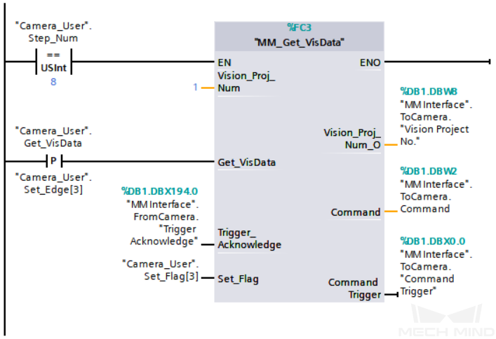
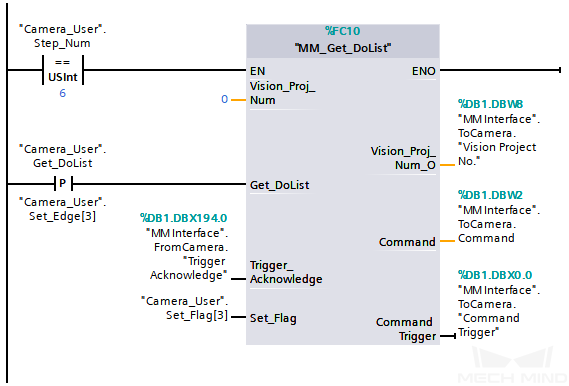
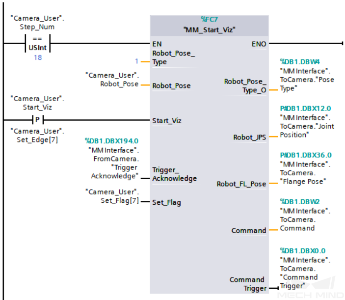
Example
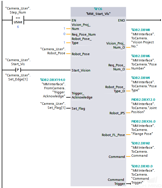
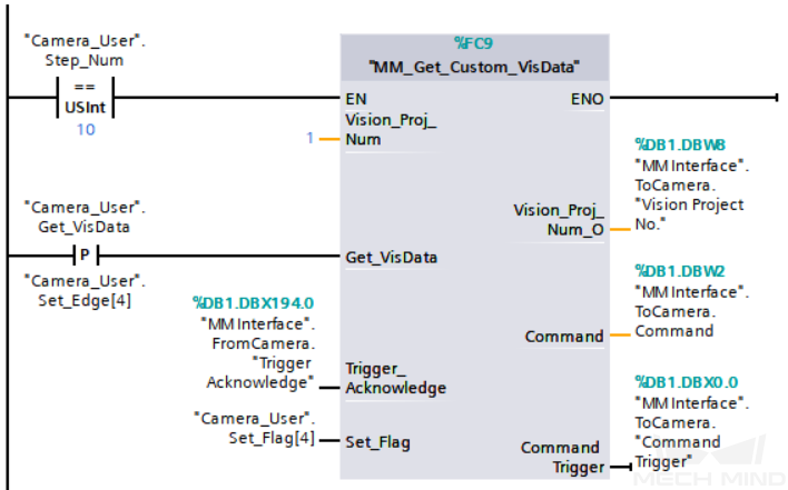
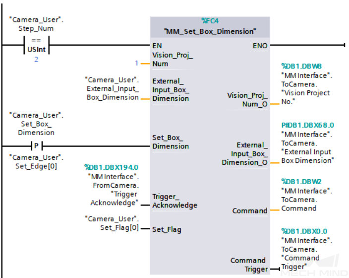
The example above indicates that "Camera_User".Step_Num is set to 6, and when a rising edge occurs on "Camera_User".Start_Vis, the PLC triggers the execution of Mech-Vision project No.1, expecting the Mech-Vision project to return all vision points or waypoints while also receiving the robot’s current joint positions and flange pose as input of Mech-Vision.
Get Vision Result
Description
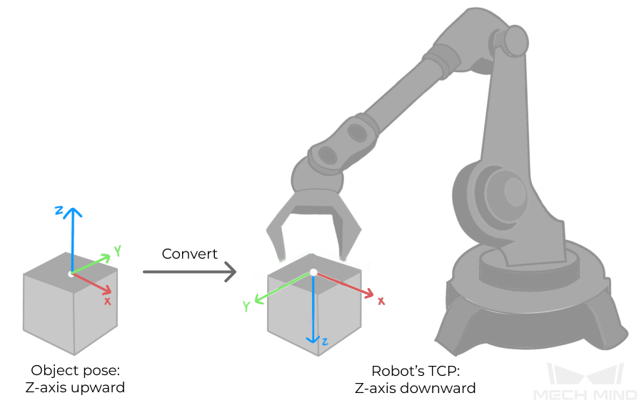
This command obtains vision result, namely, a series of vision points, from Mech-Vision. The object pose of the vision point (namely, the output of the poses port of the Output Step) will be automatically converted to the robot’s TCP by the vision system. The process is as follows.

-
Convert the object pose from a quaternion to Euler angles.
-
Rotate the object’s pose around the X-axis by 180° to orient its Z-axis downward.
Calling Sequence
This command should be called after Run Mech-Vision Project.
Modules
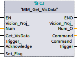
Input Parameters
Vision_Proj_Num
This parameter specifies the Mech-Vision project ID. The data type is INT. You can view the project ID of a Mech-Vision project in the Project List section of Mech-Vision. The project ID is the number before the project name.
Get_VisData
This parameter triggers the vision result to be obtained at the rising edge. The data type is BOOL.
Trigger_Acknowledge
This parameter indicates whether the Command Trigger signal has successfully triggered the vision system to run. The data type is BOOL. 1 indicates a successful trigger, while 0 means the Command Trigger signal was not received.
Input/Output Parameters
Set_Flag
This parameter specifies whether a rising edge occurred on Get_VisData. The data type is BOOL. 1 indicates that a rising edge occurred on Get_VisData, while 0 indicates that no rising edge occurred on Get_VisData.
Output Parameters
Vision_Proj_Num_O
This parameter indicates the Mech-Vision project ID. The data type is INT.
Command
This parameter indicates the command code that will be automatically assigned. The data type is INT.
Command Trigger
This parameter indicates the command switch that will be automatically triggered. The data type is BOOL.
Data returned by the MM Interface DB
Status code
This parameter indicates the name of the variable for storing the command execution status code. The data type is INT. Status code 1100 is returned for a successful command execution. If a command fails to be run, a specific error code is returned. For details, see Status Codes and Troubleshooting.
|
By default, after the robot sends this command, the vision system returns the result in 10 seconds. If the vision system fails to return any result in 10 seconds, a timeout error code is returned. To modify the default timeout period as needed, go to Robot and Communication > in the toolbar of Mech-Vision. 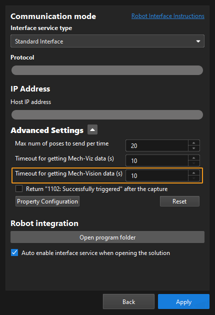
|
Status of Pose Sent
This parameter specifies whether all vision points are obtained. The data type is INT. The value is 0 or 1.
-
0: Not all vision points are obtained.
-
1: All vision points are obtained.
Number of Pose Sent
This parameter indicates the number of vision points returned by Mech-Vision. The data type is INT. Valid values: 0 to the largest positive integer.
Target Pose
This parameter indicates the poses of all vision points in the obtained vision result. The poses are TCPs. The data type is ARRAY[0..39, 0..5] of REAL.
Target Label
This parameter indicates the labels of all vision points in the obtained vision result. Labels and poses are one-to-one paired. The data type is ARRAY[0..39] of INT.
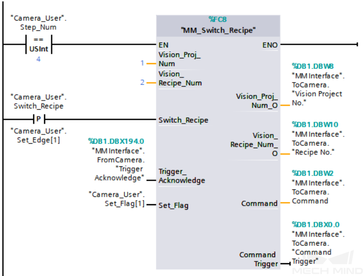
Switch Mech-Vision Parameter Recipe
Description
This command triggers Mech-Vision to switch the parameter recipe used by the project. The image below shows how to manually switch the parameter recipe for a Mech-Vision project. For details about parameter recipes, see the parameter recipe guide.

Calling Sequence
This command should be called before Run Mech-Vision Project.
Modules
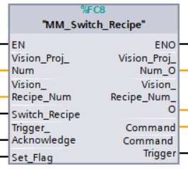
Input Parameters
Vision_Proj_Num
This parameter specifies the Mech-Vision project ID. The data type is INT. You can view the project ID of a Mech-Vision project in the Project List section of Mech-Vision. The project ID is the number before the project name.
Vision_Recipe_Num
This parameter indicates the parameter recipe ID in the Mech-Vision project. The data type is INT. For details on how to check the parameter recipe ID, see View the Parameter Recipe ID.
Switch_Recipe
This parameter triggers the switch of parameter recipe in Mech-Vision when the rising edge occurs. The data type is BOOL.
Trigger_Acknowledge
This parameter indicates whether the Command Trigger signal has successfully triggered the vision system to run. The data type is BOOL. 1 indicates a successful trigger, while 0 means the Command Trigger signal was not received.
Input/Output Parameters
Set_Flag
This parameter specifies whether a rising edge occurred on Switch_Recipe. The data type is BOOL. 1 indicates that a rising edge occurred on Switch_Recipe, while 0 indicates that no rising edge occurred on Switch_Recipe.
Output Parameters
Vision_Proj_Num_O
This parameter indicates the Mech-Vision project ID. The data type is INT.
Vision_Recipe_Num_O
This parameter indicates the parameter recipe ID in the Mech-Vision project. The data type is INT.
Command
This parameter indicates the command code that will be automatically assigned. The data type is INT.
Command Trigger
This parameter indicates the command switch that will be automatically triggered. The data type is BOOL.
Data returned by the MM Interface DB
Status code
This parameter indicates the name of the variable for storing the command execution status code. The data type is INT. Status code 1107 is returned for a successful command execution. If a command fails to be run, a specific error code is returned. For details, see Status Codes and Troubleshooting.
Get Planned Path in Mech-Vision
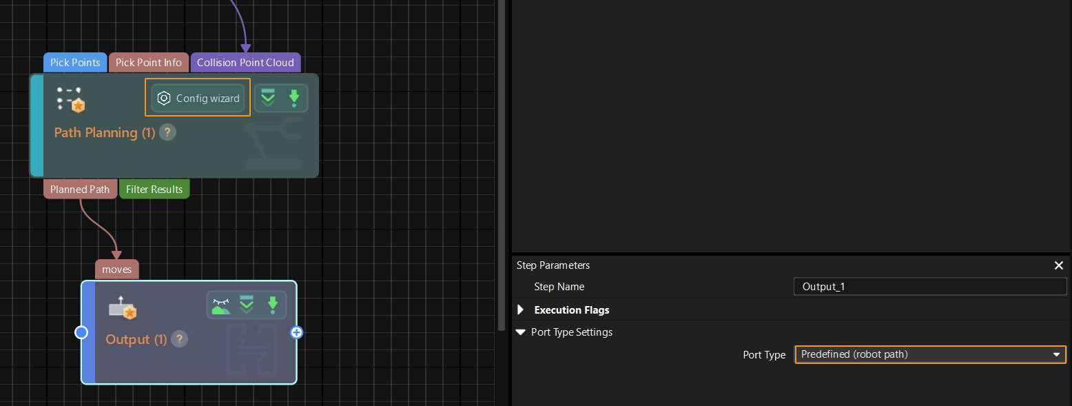
Description
This command obtains the path planned by the Mech-Vision project as a series of waypoints. The path is planned by the path planning tool, which you may enter by clicking Config wizard as shown in the image below. For details about Path Planning, see Path Planning.
| Set the Port Type parameter of the Output Step in Mech-Vision to Predefined (robot path). |
Calling Sequence
This command should be called after Run Mech-Vision Project.
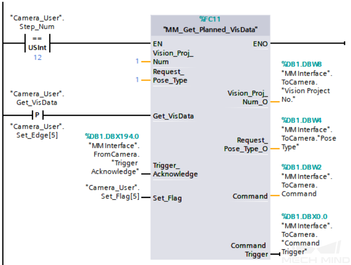
Modules
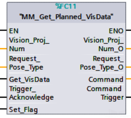
Input Parameters
Vision_Proj_Num
This parameter specifies the Mech-Vision project ID. The data type is INT. You can view the project ID of a Mech-Vision project in the Project List section of Mech-Vision. The project ID is the number before the project name.
Request_Pose_Type
This parameter specifies the type of waypoint poses to be obtained. The data type is INT. Valid values: 1 and 2.
-
1: Joint positions.
-
2: TCP.
|
Request_Pose_Type here and Robot_Pose_Type in MM_Start_Vis and MM_Start_Viz correspond to the same Pose Type parameter in MM Interface. If the set values of Request_Pose_Type and Robot_Pose_Type are different, they cannot take effect at the same time. |
Get_VisData
This parameter triggers the path planned by Mech-Vision to be obtained at the rising edge. The data type is BOOL.
Trigger_Acknowledge
This parameter indicates whether the Command Trigger signal has successfully triggered the vision system to run. The data type is BOOL. 1 indicates a successful trigger, while 0 means the Command Trigger signal was not received.
Input/Output Parameters
Set_Flag
This parameter specifies whether a rising edge occurred on Get_VisData. The data type is BOOL. 1 indicates that a rising edge occurred on Get_VisData, while 0 indicates that no rising edge occurred on Get_VisData.
Output Parameters
Vision_Proj_Num_O
This parameter indicates the Mech-Vision project ID. The data type is INT.
Request_Pose_Type_O
This parameter indicates the pose type of waypoints. The data type is INT. 1 indicates joint positions, and 2 indicates TCP.
Command
This parameter indicates the command code that will be automatically assigned. The data type is INT.
Command Trigger
This parameter indicates the command switch that will be automatically triggered. The data type is BOOL.
Data returned by the MM Interface DB
Status code
This parameter indicates the name of the variable for storing the command execution status code. The data type is INT. Status code 1103 is returned for a successful command execution. If a command fails to be run, a specific error code is returned. For details, see Status Codes and Troubleshooting.
|
By default, after the robot sends this command, the vision system returns the result in 10 seconds. If the vision system fails to return any result in 10 seconds, a timeout error code is returned. To modify the default timeout period as needed, go to Robot and Communication > in the toolbar of Mech-Vision.
|
Status of Pose Sent
This parameter specifies whether all waypoints are obtained. The data type is INT. The value is 0 or 1.
-
0: Not all waypoints are obtained.
-
1: All waypoints are obtained.
Number of Pose Sent
This parameter indicates the number of waypoints returned by Mech-Vision. The data type is INT. Valid values: 0 to the largest positive integer.
Index of Vision Picking Point
The sequence number of the Vision Move waypoint (the waypoint corresponding to the Vision Move step of the path planning tool) in the path. The data type is INT. If the waypoint does not exist in the path, the petameter value is 0.
If the planned path consists of the following waypoints in sequence: Fixed-Point Move_1, Fixed-Point Move_2, Vision Move, and Fixed-Point Move_3, the sequence number of the Vision Move waypoint is 3.
Target Pose
This parameter indicates the poses of all waypoints in the obtained planned path. The data type is ARRAY[0..39, 0..5] of REAL.
Target Label
This parameter indicates the labels of all waypoints in the obtained planned path. Labels and poses are one-to-one paired. The data type is ARRAY[0..39] of INT.
Target Tool ID
This parameter indicates the tool IDs of all waypoints in the obtained planned path. The tool IDs and poses are one-to-one paired. The data type is ARRAY[0..39] of INT.
Get Mech-Vision Custom Data
Description
This command obtains data from the custom port(s) of the “Output” Step in Mech-Vision. One command call saves all port data of the Output Step to the specified register.
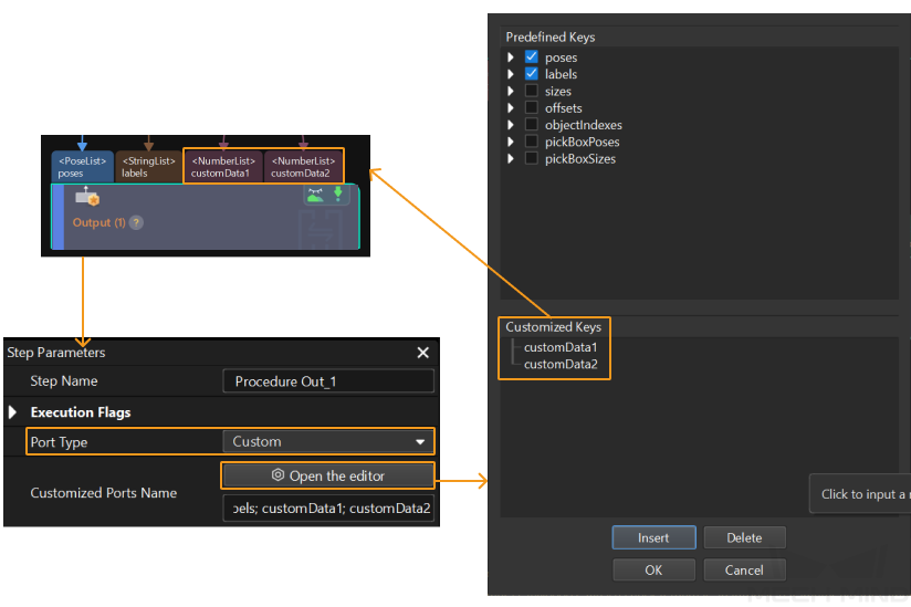
Select the Output step, set Port Type to Custom, and then click Open the editor to go to the custom port configuration window. The Customized Keys section of the window displays custom port names, such as customeData1 and customeData2, as shown in the following figure.
|
| The number of custom ports cannot exceed 10. The obtained custom data is sorted in a case-sensitive alphabetical order of ports. |
Calling Sequence
This command should be called after Run Mech-Vision Project.
Modules
Input Parameters
Vision_Proj_Num
This parameter specifies the Mech-Vision project ID. The data type is INT. You can view the project ID of a Mech-Vision project in the Project List section of Mech-Vision. The project ID is the number before the project name.
Get_VisData
This parameter triggers custom data of Mech-Vision to be obtained at the rising edge. The data type is BOOL.
Trigger_Acknowledge
This parameter indicates whether the Command Trigger signal has successfully triggered the vision system to run. The data type is INT. 1 indicates a successful trigger, while 0 means the Command Trigger signal was not received.
Input/Output Parameters
Set_Flag
This parameter specifies whether a rising edge occurred on Get_VisData. The data type is BOOL. 1 indicates that a rising edge occurred on Get_VisData, while 0 indicates that no rising edge occurred on Get_VisData.
Output Parameters
Vision_Proj_Num_O
This parameter indicates the Mech-Vision project ID. The data type is INT.
Command
This parameter indicates the command code that will be automatically assigned. The data type is INT.
Command Trigger
This parameter indicates the command switch that will be automatically triggered. The data type is INT.
Data returned by the MM Interface DB
Status code
This parameter indicates the name of the variable for storing the command execution status code. The data type is INT. Status code 1100 is returned for a successful command execution. If a command fails to be run, a specific error code is returned. For details, see Status Codes and Troubleshooting.
Status of Pose Sent
This parameter specifies whether all vision points are obtained. The data type is INT. The value is 0 or 1.
-
0: Not all vision points are obtained.
-
1: All vision points are obtained.
Number of Pose Sent
This parameter stores the number of vision points returned by Mech-Vision. The data type is INT.
Target Pose
This parameter indicates the poses of all vision points in the obtained vision result. The poses are TCPs. The data type is ARRAY[0..39, 0..5] of REAL.
Target Label
This parameter indicates the labels of all vision points in the obtained vision result. Labels and poses are one-to-one paired. The data type is ARRAY[0..39] of INT.
Custom Data Output
This parameter indicates the custom data of each vision point in the obtained vision result. Custom data and poses are one-to-one paired. The data type is ARRAY[0..39, 0..9] of REAL.
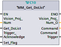
Get Gripper DO List
Description
This command obtains the control signal list for the multi-section vacuum gripper from the Mech-Vision or Mech-Viz project. Before using this command, you must perform the following configurations in Mech-Vision or Mech-Viz.
-
Configure the Mech-Vision project
-
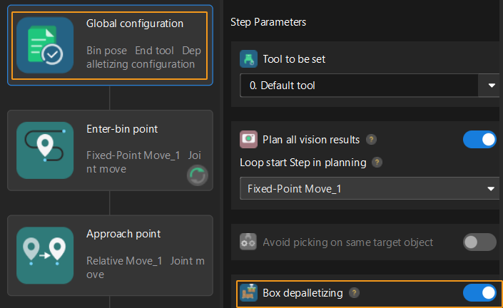
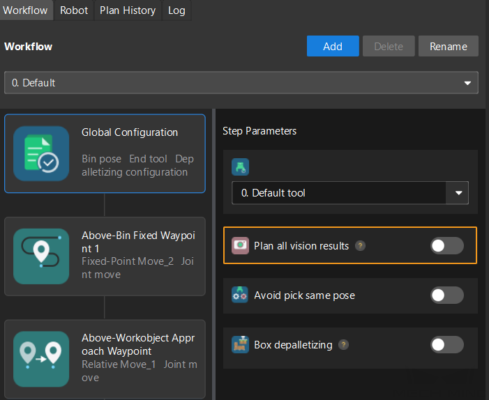
In the Path Planning Step, click Config wizard. In Global configuration, enable Box depalletizing.
-
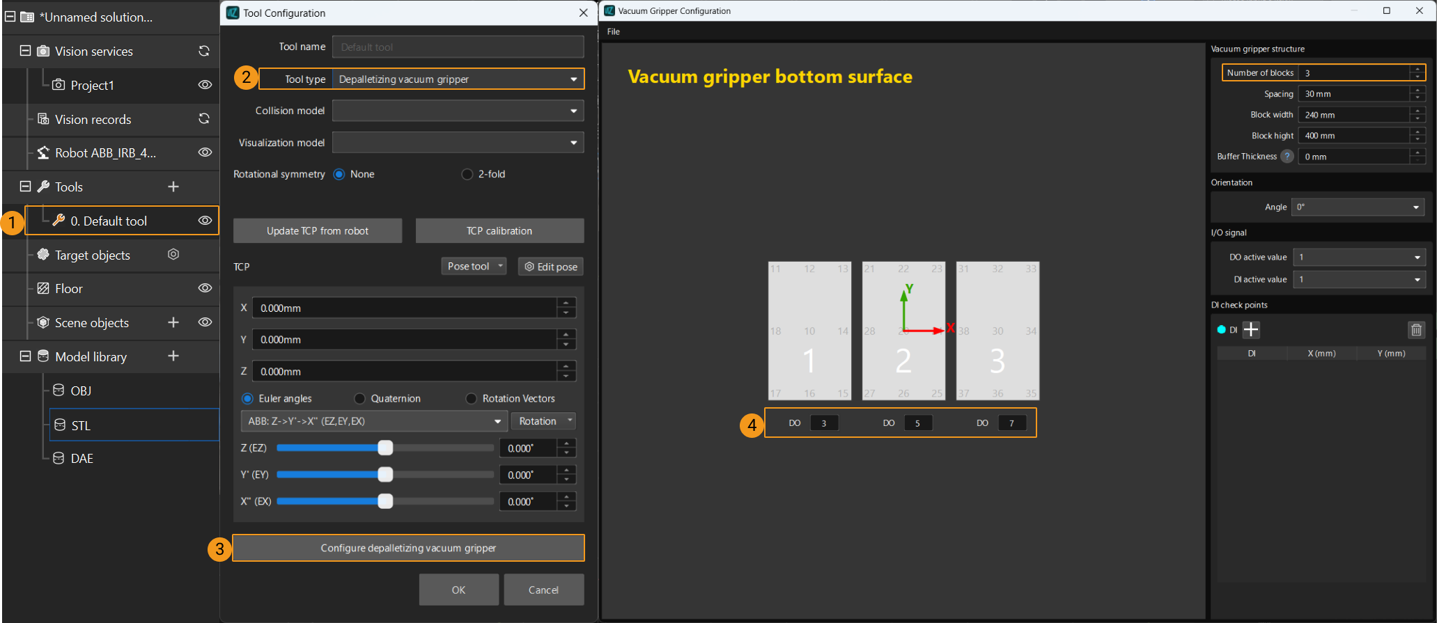
In the Path Planning Step, click Config wizard, and then double-click the name of the robot tool. In the pop-up window, select Depalletizing vacuum gripper for Tool type, click Configure depalletizing vacuum gripper, and then configure DO signals according to needs.

-
-
Configure the Mech-Viz project
-
In the Vision Move Step of Mech-Viz, set Select Picking Method to Box depalletizing.

-
In Mech-Viz, double-click the tool name, select Depalletizing vacuum gripper for Tool type, click Configure depalletizing vacuum gripper, and then configure the DO signals according to needs.
-
Calling Sequence
This command must be called before the Get Planned Path in Mech-Vision or Get Planned Path in Mech-Viz command. This means that the PLC must obtain the planned path and then obtain gripper DO signals of the Vision Move waypoint.
Modules
Input Parameters
Vision_Proj_Num
This parameter specifies the source of the DO signal list. The data type is INT. Valid values: 0 to the largest positive integer.
-
0: Get DO signal list from Mech-Viz.
-
A positive integer: Get DO signal list from Mech-Vision. The positive integer is the Mech-Vision project ID.
Depalletize_Tool_Section_Count
This parameter indicates the number of vacuum gripper sections. The data type is INT.
Get_DoList
This parameter triggers gripper DO signals to be obtained at the rising edge. The data type is BOOL.
Trigger_Acknowledge
This parameter indicates whether the Command Trigger signal has successfully triggered the vision system to run. The data type is BOOL. 1 indicates a successful trigger, while 0 means the Command Trigger signal was not received.
Input/Output Parameters
Set_Flag
This parameter specifies whether a rising edge occurred on Get_DoList. The data type is BOOL. 1 indicates that a rising edge occurred on Get_DoList, while 0 indicates that no rising edge occurred on Get_DoList.
Output Parameters
Vision_Proj_Num_O
This parameter indicates the source of the DO signal list. The data type is INT.
Depalletize_Tool_Section_Count_O
This parameter indicates the number of vacuum gripper sections. The data type is INT.
Command
This parameter indicates the command code that will be automatically assigned. The data type is INT.
Command Trigger
This parameter indicates the command switch that will be automatically triggered. The data type is BOOL.
Data returned by the MM Interface DB
Status code
This parameter indicates the name of the variable for storing the command execution status code. The data type is INT. If the DO signal list is successfully obtained from Mech-Vision, the status code is 1106. If the DO signal list is successfully obtained from Mech-Viz, the status code is 2102. If a command fails to be run, a specific error code is returned. For details, see Status Codes and Troubleshooting.
DO
This parameter indicates the 64 DO signals returned by this command. The data type is ARRAY[0..63] of INT.
The DO signals returned by this command vary based on the deployed project.
-
Gripper DO signals planned by the Mech-Vision project
-
Under Global Configuration of the path planning tool, if Plan all vision results is disabled, this command returns 64 gripper DO signals that are planned in this round. Valid DO signals are non-negative integers ranging from 0 to 999. Invalid DO signals are -1, which serves as a placeholder.
For example, valid DO signals in the table below are 1, 3, 5, and 6, which means that the robot will set the values of these DO signals to ON.
1st
2nd
3rd
4th
5th
6th
7th
8th
…
63rd
64th
1
3
5
6
-1
-1
-1
-1
…
-1
-1
-
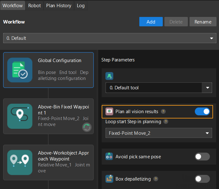
Under Global Configuration of the path planning tool, if Plan all vision results is enabled, Mech-Vision can perform multiple rounds of planning based on the same vision result. The 64 gripper DO signals returned by this command are obtained during all rounds of planning. In this case, you can use the number of vacuum gripper sections to differentiate the gripper DO signals obtained during each round of planning.
For example, if the number of vacuum gripper sections is 4 and the command returns 64 DO signals in total, each 4 DO signals are multi-section vacuum gripper signals obtained during each round of planning.
First round of planning
Second round of planning
…
16th round of planning
1st
2nd
3rd
4th
5th
6th
7th
8th
…
61st
62nd
63rd
64th
1
3
4
-1
1
4
-1
-1
…
-1
-1
-1
-1
-
-
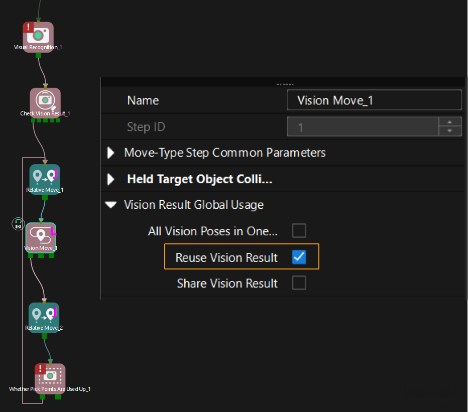
Gripper DO signals planned by the Mech-Viz project
-
If Reuse Vision Result is not selected for the Vision Move Step, this command returns 64 gripper DO signals that are planned during this round. Valid DO signals are non-negative integers ranging from 0 to 999. Invalid DO signals are -1, which serves as a placeholder.

For example, valid DO signals in the table below are 1, 3, 5, and 6, which means that the robot will set the values of these DO signals to ON.
1st
2nd
3rd
4th
5th
6th
7th
8th
…
63rd
64th
1
3
5
6
-1
-1
-1
-1
…
-1
-1
-
If Reuse Vision Result is selected for the Vision Move Step and the Vision Move Step is used in a loop, Mech-Viz can perform multiple rounds of planning based on the same vision result. The 64 gripper DO signals returned by this command are obtained during all rounds of planning. In this case, you can use the number of vacuum gripper sections to differentiate the gripper DO signals obtained during each round of planning.
For example, if the number of vacuum gripper sections is 4 and the command returns 64 DO signals in total, each 4 DO signals are multi-section vacuum gripper signals obtained during each round of planning.
First round of planning
Second round of planning
…
16th round of planning
1st
2nd
3rd
4th
5th
6th
7th
8th
…
61st
62nd
63rd
64th
1
3
4
-1
1
4
-1
-1
…
-1
-1
-1
-1
-
Run Mech-Viz Project
Description
This command triggers the Mech-Viz project to run. Mech-Viz plans the robot’s motion path based on the vision result output by Mech-Vision.
| Right-click the project name in the project resource panel in Mech-Viz and select Autoload Project. |
Modules
Input Parameters
Robot_Pose_Type
This parameter specifies the way in which the real robot pose is sent to the Mech-Viz project. Valid values: 0, 1, and 2. The following table describes the details. The data type is INT.
Robot_Pose
This parameter specifies the pose of the robot. The data type is ARRAY[0..1, 0..5] of REAL. The data structure of this parameter is a two-dimensional array. Array[0] represents the robot’s joint positions, and Array[1] represents the robot’s flange pose.
The following table explains the relationship between Robot_Pose_Type and Robot_Pose.
| Robot_Pose_Type | Robot_Pose | Description | Applicable scenario |
|---|---|---|---|
0 |
[[0,0,0,0,0,0]],[0,0,0,0,0,0]] |
This command does not need to send the robot pose to the Mech-Viz project. The simulated robot in the Mech-Viz project will move from the set home position to the first waypoint. |
This setting is recommended when the camera is mounted in eye to hand mode. |
1 |
Current joint positions and flange pose of the robot |
In this command, the robot sends its current joint positions and flange pose to the Mech-Viz project. The simulated robot in Mech-Viz moves from the input joint positions to the first waypoint. |
This setting is recommended when the camera is mounted in eye in hand mode. |
2 |
Joint positions of the start point of the planned path |
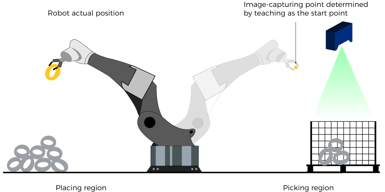
In this command, the robot sends the joint positions of a teach point (the custom joint positions, instead of the current joint positions) to the Mech-Viz project. The Mech-Viz project uses the input joint positions to plan the next path in advance while the robot is not in the camera capture region, as shown in the following figure. The simulated robot in Mech-Viz moves from the input joint positions to the first waypoint. |
This setting is recommended when the camera is mounted in eye to hand mode. |
If the camera is mounted in eye to hand mode, option 2 is recommended for Robot_Pose_Type. Why?
In eye to hand mode, the camera can perform image capturing for the next round of path planning before the robot returns to the image capture region and picking region, thus shortening the cycle time. The image below demonstrates how a robot works in the placing region.
If Robot_Pose_Type is set to 1, the robot will send the current pose to Mech-Viz. It is possible that the real robot moves to other positions before reaching the first waypoint. However, the simulated robot moves directly to the first waypoint of the Mech-Viz project from the pose sent by the robot. Consequently, there may be a mismatch between the paths of the real robot and simulated robot. This mismatch can potentially lead to unpredicted safety hazards, especially if a collision is detected in the path of the simulated robot.
On the other hand, if Robot_Pose_Type is set to 2, the robot will send the image-capturing pose set by teaching to Mech-Viz. Thus, the real robot can trigger the next round of path planning in Mech-Viz when the real robot is in the image-capturing region and the cycle time can be shortened.
This is why when the camera is mounted in eye to hand mode, option 2 is recommended for Robot_Pose_Type.
Start_Viz
This parameter triggers the Mech-Viz project to run at the rising edge. The data type is BOOL.
Trigger_Acknowledge
This parameter indicates whether the Command Trigger signal has successfully triggered the vision system to run. The data type is BOOL. 1 indicates a successful trigger, while 0 means the Command Trigger signal was not received.
Input/Output Parameters
Set_Flag
This parameter specifies whether a rising edge occurred on Start_Viz. The data type is BOOL. 1 indicates that a rising edge occurred on Start_Viz, while 0 indicates that no rising edge occurred on Start_Viz.
Output Parameters
Robot_Pose_Type_O
This parameter indicates the way in which the real robot pose is sent to the Mech-Viz project. The data type is INT. Valid values: 0, 1, and 2.
Robot_JPS
This parameter indicates the joint positions of the robot. The data type is ARRAY[0..5] of REAL.
Robot_FL_Pose
This parameter indicates the flange pose of the robot. The data type is ARRAY[0..5] of REAL.
Command
This parameter indicates the command code that will be automatically assigned. The data type is INT.
Command Trigger
This parameter indicates the command switch that will be automatically triggered. The data type is BOOL.
Data returned by the MM Interface DB
Status code
This parameter indicates the name of the variable for storing the command execution status code. The data type is INT. Status code 2103 is returned for a successful command execution. If a command fails to be run, a specific error code is returned. For details, see Status Codes and Troubleshooting.
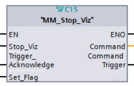
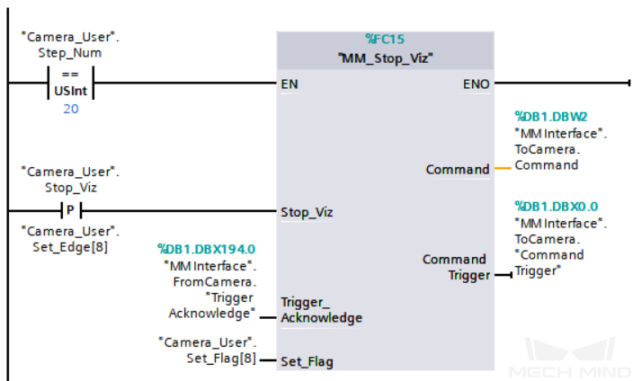
Stop Mech-Viz Project
Calling Sequence
This command should be called after Run Mech-Viz Project.
Modules
Input Parameters
Stop_Viz
This parameter triggers the Mech-Viz project to stop at the rising edge. The data type is BOOL.
Trigger_Acknowledge
This parameter indicates whether the Command Trigger signal has successfully triggered the vision system to run. The data type is BOOL. 1 indicates a successful trigger, while 0 means the Command Trigger signal was not received.
Input/Output Parameters
Set_Flag
This parameter specifies whether a rising edge occurred on Stop_Viz. The data type is BOOL. 1 indicates that a rising edge occurred on Stop_Viz, while 0 indicates that no rising edge occurred on Stop_Viz.
Output Parameters
Command
This parameter indicates the command code that will be automatically assigned. The data type is INT.
Command Trigger
This parameter indicates the command switch that will be automatically triggered. The data type is BOOL.
Data returned by the MM Interface DB
Status code
This parameter indicates the name of the variable for storing the command execution status code. The data type is INT. Status code 2104 is returned for a successful command execution. If a command fails to be run, a specific error code is returned. For details, see Status Codes and Troubleshooting.
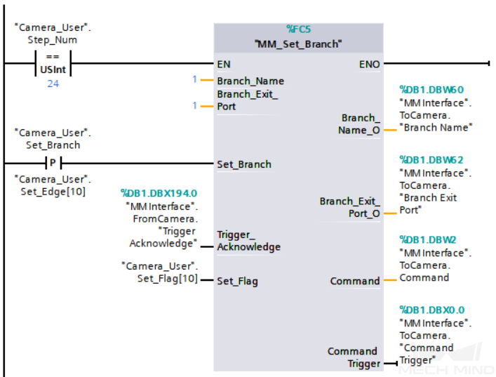
Set the Exit Port for the Branch by Msg Step in Mech-Viz
Description
This command sets the exit port for the Branch by Msg Step. When the next Step is a Branch by Msg Step, the Mech-Viz project will wait for this command to specify the exit port.
Calling Sequence
This command should be called after Run Mech-Viz Project.
Modules
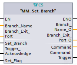
Input Parameters
Branch_Name
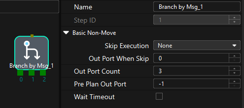
This parameter specifies the “Branch by Msg” Step by its ID. The data type is INT. Valid values: positive integers. The Step ID is displayed in the Step parameter panel. For example, the Step ID of the Step in the image above is 1.
Branch_Exit_Port
This parameter indicates the exit port of the Branch by Msg Step. The data type is INT. Valid values: positive integers. When the parameter value is set to N, the Mech-Viz project exits from the port with an ID of N-1 of the Branch by Msg Step.
Set_Branch
This parameter triggers the exit port of the Branch by Msg Step to be set in the Mech-Viz project at the rising edge. The data type is BOOL.
Trigger_Acknowledge
This parameter indicates whether the Command Trigger signal has successfully triggered the vision system to run. The data type is BOOL. 1 indicates a successful trigger, while 0 means the Command Trigger signal was not received.
Input/Output Parameters
Set_Flag
This parameter specifies whether a rising edge occurred on Set_Branch. The data type is BOOL. 1 indicates that a rising edge occurred on Set_Branch, while 0 indicates that no rising edge occurred on Set_Branch.
Output Parameters
Branch_Name_O
This parameter indicates the Step ID of the Branch by Msg Step. The data type is INT.
Branch_Exit_Port_O
This parameter indicates the exit port of the Branch by Msg Step. The data type is INT.
Command
This parameter indicates the command code that will be automatically assigned. The data type is INT.
Command Trigger
This parameter indicates the command switch that will be automatically triggered. The data type is BOOL.
Data returned by the MM Interface DB
Status code
This parameter indicates the name of the variable for storing the command execution status code. The data type is INT. Status code 2105 is returned for a successful command execution. If a command fails to be run, a specific error code is returned. For details, see Status Codes and Troubleshooting.
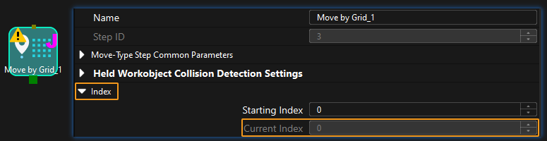
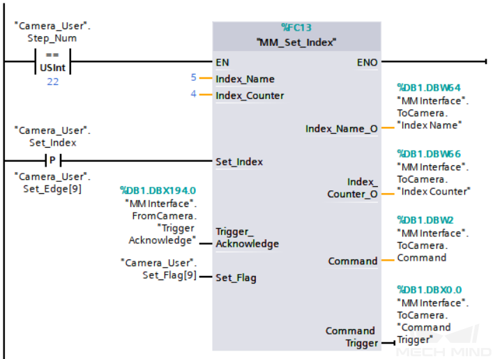
Set Current Index in Mech-Viz
Description
This command sets the value of the Current Index parameter of index-type Steps. Index-type Steps are Steps that include the Index section, which include Move by Grid, Move by List, Custom Pallet Pattern, and Predefined Pallet Pattern.
Calling Sequence
Index-type Steps are often preceded by a Branch by Msg Step. The PLC should call commands in this order: Run Mech-Viz Project, Set Current Index in Mech-Viz, and Set the Exit Port for the Branch by Msg Step in Mech-Viz. This is to ensure that Mech-Viz has enough time to set the Current Index value.
Modules
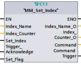
Input Parameters
Index_Name
This parameter specifies the Step ID of the Index-type Step. The data type is INT. Valid values: positive integers. The Step ID is displayed in the Step parameter panel. For example, the Step ID of the Step in the image above is 3.
Index_Counter
This parameter sets the value of the Current Index parameter of index-type Steps. The data type is INT. Valid values: positive integers. When this parameter value is set to N, the current index of the corresponding Step is N-1.
Set_Index
This parameter triggers the Current Index value to be set in the Mech-Viz project at the rising edge. The data type is BOOL.
Trigger_Acknowledge
This parameter indicates whether the Command Trigger signal has successfully triggered the vision system to run. The data type is BOOL. 1 indicates a successful trigger, while 0 means the Command Trigger signal was not received.
Input/Output Parameters
Set_Flag
This parameter specifies whether a rising edge occurred on Set_Index. The data type is BOOL. 1 indicates that a rising edge occurred on Set_Index, while 0 indicates that no rising edge occurred on Set_Index.
Output Parameters
Index_Name_O
This parameter indicates the Step ID of the index-type Step. The data type is INT.
Index_Counter_O
This parameter indicates the Current Index value of the index-type Step. The data type is INT.
Command
This parameter indicates the command code that will be automatically assigned. The data type is INT.
Command Trigger
This parameter indicates the command switch that will be automatically triggered. The data type is BOOL.
Data returned by the MM Interface DB
Status code
This parameter indicates the name of the variable for storing the command execution status code. The data type is INT. Status code 2106 is returned for a successful command execution. If a command fails to be run, a specific error code is returned. For details, see Status Codes and Troubleshooting.
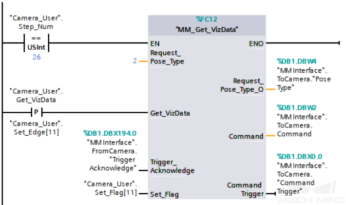
Get Planned Path in Mech-Viz
Description
This command obtains the path planned by the Mech-Viz project as a series of waypoints.
|
Waypoint: Each point that the robot reaches when moving along the planned path. A waypoint has information including the robot pose, label, motion type, and velocity. Waypoints can be divided into two categories:
|
Calling Sequence
This command should be called after Run Mech-Viz Project.
Modules
Input Parameters
Request_Pose_Type
This parameter specifies the type of waypoint poses to be obtained. The data type is INT. Valid values: 1 and 2.
-
1: Joint positions.
-
2: TCP.
|
Request_Pose_Type here and Robot_Pose_Type in MM_Start_Vis and MM_Start_Viz correspond to the same Pose Type parameter in MM Interface. If the set values of Request_Pose_Type and Robot_Pose_Type are different, they cannot take effect at the same time. |
Get_VizData
This parameter triggers the path planned by Mech-Viz to be obtained at the rising edge. The data type is BOOL.
Trigger_Acknowledge
This parameter indicates whether the Command Trigger signal has successfully triggered the vision system to run. The data type is BOOL. 1 indicates a successful trigger, while 0 means the Command Trigger signal was not received.
Input/Output Parameters
Set_Flag
This parameter specifies whether a rising edge occurred on Get_VizData. The data type is BOOL. 1 indicates that a rising edge occurred on Get_VizData, while 0 indicates that no rising edge occurred on Get_VizData.
Output Parameters
Request_Pose_Type_O
This parameter indicates the pose type of waypoints. The data type is INT. 1 indicates joint positions, and 2 indicates TCP.
Robot_JPS
This parameter indicates the joint positions of the robot. The data type is ARRAY[0..5] of REAL.
Robot_FL_Pose
This parameter indicates the flange pose of the robot. The data type is ARRAY[0..5] of REAL.
Command
This parameter indicates the command code that will be automatically assigned. The data type is INT.
Command Trigger
This parameter indicates the command switch that will be automatically triggered. The data type is BOOL.
Data returned by the MM Interface DB
Status code
This parameter indicates the name of the variable for storing the command execution status code. The data type is INT. Status code 2100 is returned for a successful command execution. If a command fails to be run, a specific error code is returned. For details, see Status Codes and Troubleshooting.
|
By default, after the robot sends this command, the vision system returns the result in 10 seconds. If the vision system fails to return any result in 10 seconds, a timeout error code is returned. To modify the default timeout period as needed, go to Robot and Communication > in the toolbar of Mech-Vision. 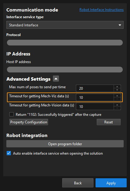
|
Status of Pose Sent
This parameter specifies whether all waypoints are obtained. The data type is INT. The value is 0 or 1.
-
0: Not all waypoints are obtained.
-
1: All waypoints are obtained.
Number of Pose Sent
This parameter indicates the number of waypoints returned by Mech-Viz. The data type is INT. Valid values: 0 to the largest positive integer.
Index of Vision Picking Point
The sequence number of the Vision Move waypoint (i.e., the waypoint corresponding to the Vision Move Step in the Mech-Viz project) in the path. The data type is INT. If the waypoint does not exist in the path, the petameter value is 0.
If the planned path consists of the following waypoints in sequence: Fixed-Point Move_1, Fixed-Point Move_2, Vision Move, and Fixed-Point Move_3, the sequence number of the Vision Move waypoint is 3.
Target Pose
This parameter indicates the poses of all waypoints in the obtained planned path. The data type is ARRAY[0..39, 0..5] of REAL.
Target Label
This parameter indicates the labels of all waypoints in the obtained planned path. Labels and poses are one-to-one paired. The data type is ARRAY[0..39] of INT.
Target Tool ID
This parameter indicates the tool IDs of all waypoints in the obtained planned path. The tool IDs and poses are one-to-one paired. The data type is ARRAY[0..39] of INT.
Input Object Dimensions to Mech-Vision Project
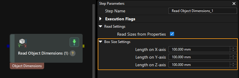
Description
This command dynamically inputs object dimensions into the Mech-Vision project. The object dimensions are the values of the Box Size Settings parameters in the Read Object Dimensions Step, as shown in the following figure.
| When you use this command, only one Read Object Dimensions Step is allowed in the Mech-Vision project. Otherwise, the vision system will return an error. |
Calling Sequence
This command should be called before Run Mech-Vision Project.
Modules
Input Parameters
Vision_Proj_Num
This parameter specifies the Mech-Vision project ID. The data type is INT. You can view the project ID of a Mech-Vision project in the Project List section of Mech-Vision. The project ID is the number before the project name.
External_Input_Box_Dimension
This parameter inputs the length, width, and height of the object to the Mech-Vision project. The length, width, and height are measured in millimeters (mm). These values are read by the Read Object Dimensions Step and set for the parameters Length on X-axis, Length on Y-axis and Length on Z-axis. The data type is ARRAY[0..2] of REAL.
Set_Box_Dimension
This parameter triggers the object dimensions to be input to the Mech-Vision project at the rising edge. The data type is BOOL.
Trigger_Acknowledge
This parameter indicates whether the Command Trigger signal has successfully triggered the vision system to run. The data type is BOOL. 1 indicates a successful trigger, while 0 means the Command Trigger signal was not received.
Input/Output Parameters
Set_Flag
This parameter specifies whether a rising edge occurred on Set_Box_Dimension. The data type is BOOL. 1 indicates that a rising edge occurred on Set_Box_Dimension, while 0 indicates that no rising edge occurred on Set_Box_Dimension.
Output Parameters
Vision_Proj_Num_O
This parameter indicates the Mech-Vision project ID. The data type is INT.
External_Input_Box_Dimension_O
This parameter indicates the object dimensions input to the Mech-Vision project. The data type is ARRAY[0..2] of REAL.
Command
This parameter indicates the command code that will be automatically assigned. The data type is INT.
Command Trigger
This parameter indicates the command switch that will be automatically triggered. The data type is BOOL.
Data returned by the MM Interface DB
Status code
This parameter indicates the name of the variable for storing the command execution status code. The data type is INT. Status code 1108 is returned for a successful command execution. If a command fails to be run, a specific error code is returned. For details, see Status Codes and Troubleshooting.
Get Message from Notify Step
Description
When the Mech-Vision project or Mech-Viz project is executing the Notify Step, the vision system returns the message predefined in the Notify Step.
| When the Notify Step is executed in the Mech-Vision or Mech-Viz project, the message remains in the buffer of the vision system for only three second. Therefore, you should consider the timing of calling this command to ensure successful message retrieval. Additionally, after the PLC receives the message, the program should trigger the variable “CameraIO”.MM.ToCamera.CLEAR_NOTIFY to clear the register data. |
Before sending this command, complete the following settings for the Notify Step.
-
For a Notify Step in the Mech-Vision project:
-
Connect the Notify Step to the right side of another Step. The Output Step is used in the example in the image below.
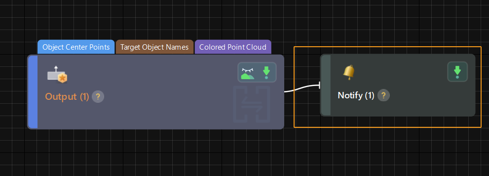
-
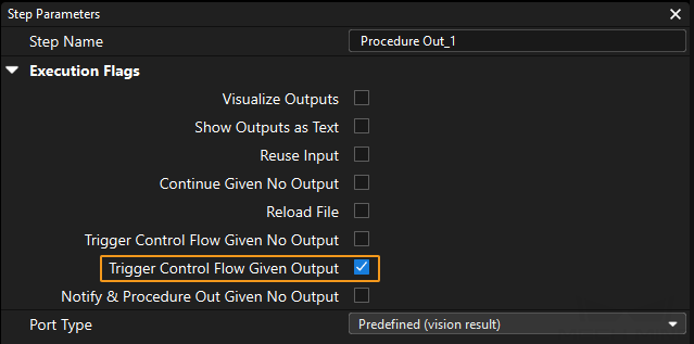
Select Trigger Control Flow Given Output in the parameter panel of the Output Step.
-
In the parameter panel of the Notify Step, enter Standard Interface Notify (the value cannot be modified) for Service Name. Enter a positive integer for Message, for example, 1001.

-
-
For a Notify Step in the Mech-Viz project:
-
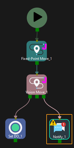
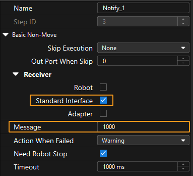
Connect the Notify Step to a proper Step in the workflow.
-
In the parameter panel of the Notify Step, select Standard Interface. Enter a positive integer for Message, for example, 1000.
-
Calling Sequence
This command should be called after Run Mech-Vision Project or Run Mech-Viz Project.
Modules
Input Parameters
Get_Notify
This parameter triggers the message of the Notify Step to be obtained at the rising edge. The data type is BOOL.
Trigger_Acknowledge
This parameter indicates whether the Command Trigger signal has successfully triggered the vision system to run. The data type is BOOL. 1 indicates a successful trigger, while 0 means the Command Trigger signal was not received.
Input/Output Parameters
Set_Flag
This parameter specifies whether a rising edge occurred on Get_Notify. The data type is BOOL. 1 indicates that a rising edge occurred on Get_Notify, while 0 indicates that no rising edge occurred on Get_Notify.
Example
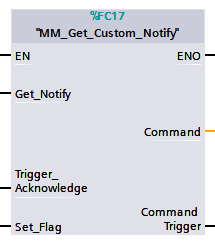
For example, the message set in the “Notify” Step is 777, and the PLC is obtaining a message in the automatic mode.
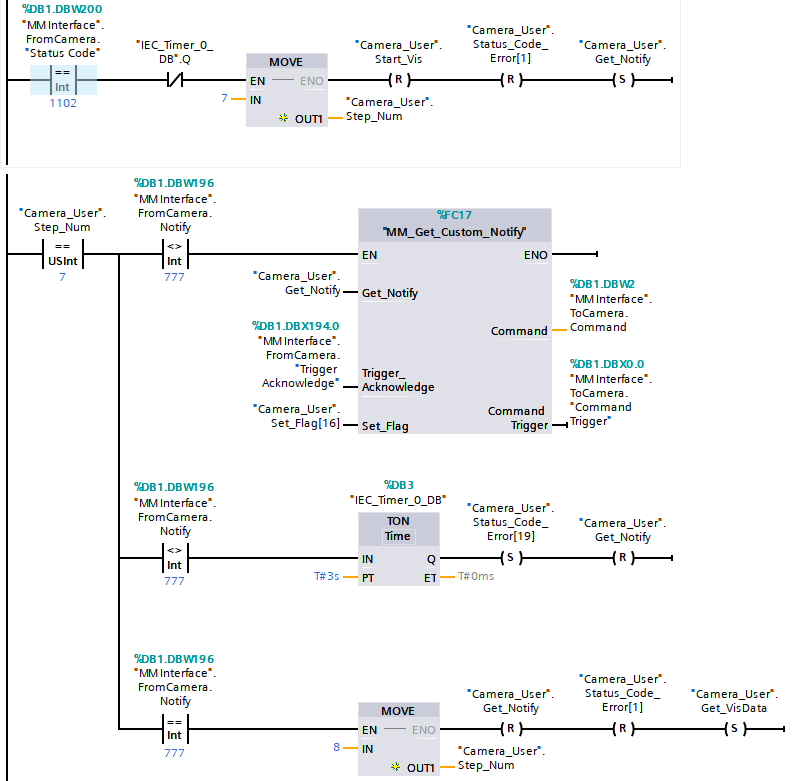
The example above indicates that in automatic mode, "Camera_User".Step_Num is set to 7. At this point, "MM Interface".FromCamera.Notify is not equal to 777, and "MM_Get_Custom_Notify" is enabled. When a rising edge occurs on the variable "Camera_User".Get_Notify, the message preset in the Notify Step is retrieved. If the message retrieval is successful, the value of “MM Modbus TCP Interface”.Notify changes to 777. Otherwise, if the value remains unchanged, the PLC will prompt an error after 3 seconds.
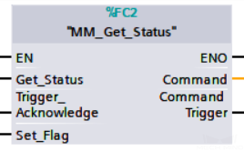
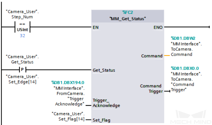
Get Project Status
Modules
Input Parameters
Get_Status
This parameter checks if the Mech-Vision project is ready at the rising edge. The data type is BOOL.
Trigger_Acknowledge
This parameter indicates whether the Command Trigger signal has successfully triggered the vision system to run. The data type is BOOL. 1 indicates a successful trigger, while 0 means the Command Trigger signal was not received.
Input/Output Parameters
Set_Flag
This parameter specifies whether a rising edge occurred on Get_Status. The data type is BOOL. 1 indicates that a rising edge occurred on Get_Status, while 0 indicates that no rising edge occurred on Get_Status.
Output Parameters
Command
This parameter indicates the command code that will be automatically assigned. The data type is INT.
Command Trigger
This parameter indicates the command switch that will be automatically triggered. The data type is BOOL.
Data returned by the MM Interface DB
Status code
This parameter indicates the name of the variable for storing the command execution status code. The data type is INT. Status code 1101 is returned for a successful command execution. If a command fails to be run, a specific error code is returned. For details, see Status Codes and Troubleshooting.
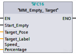
Clear Waypoint Data
Modules
Input Parameters
Start_Empty
This parameter triggers the obtained poses, labels, and tool IDs to be cleared. This parameter will take effect when it is set. The data type is BOOL.
Input/Output Parameters
Target_Pose
This parameter indicates the poses of the obtained waypoints or vision points. The data type is ARRAY[0..19, 0..5] OF DINT.
Target_Label
This parameter indicates the labels of the obtained waypoints or vision points. The data type is ARRAY[0..19] OF UDINT.
Target_Tool_ID
This parameter indicates the tool IDs of the obtained waypoints or vision points. The data type is ARRAY[0..19] OF UDINT.
| This command should not always be in the enabled status. As IN/OUT parameters, Target_Pose, Target_Label and Target_Tool_ID will be read/written in each scan cycle if the command remains in the enabled status. Consequently, data already sent by the vision system might be overwritten. |
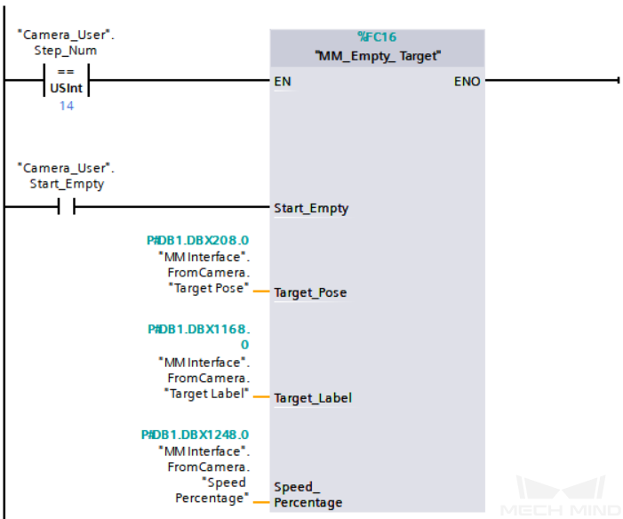
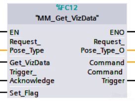
Get Vision Move Data or Custom Output Data
This command obtains Vision Move output from the Mech-Vision project, or the Vision Move output or custom output from the Mech-Viz project.
|
-
Mech-Vision projects: Vision Move data refers to data output by the Vision Move Step in the path planning tool, which you may enter from the Path Planning Step. Vision Move data includes labels of picked workobjects, number of picked workobjects, number of workobjects to be picked this time, edge or corner ID of vacuum gripper, TCP offset, orientation of workobject group, orientation of workobject, and dimensions of workobject group.
-
Mech-Viz projects:
-
Vision Move data refers to data output by the Vision Move Step in Mech-Viz, including the labels of picked workobjects, number of picked workobjects, number of workobjects to be picked this time, edge or corner ID of vacuum gripper, TCP offset, orientation of workobject group, orientation of workobject, and dimensions of workobject group.
-
Custom data: Refers to data output by the custom-type port(s) of the “Output” Step in Mech-Vision and then forwarded by Mech-Viz.
Select the Output step, set Port Type to Custom, and then click Open the editor to go to the custom port configuration window. The Customized Keys section of the window displays custom port names, such as customeData1 and customeData2, as shown in the following figure.
-
Data output from Predefined Keys, such as poses, labels, sizes, offsets, is not custom data.
-
You must set Port Type of the Output step to Custom and select the poses port in the Predefined Keys section in Mech-Vision.
-
-
Calling Sequence
This command should be called after Run Mech-Vision Project or Run Mech-Viz Project.
Input Parameters
Vision_Proj_Num
This parameter specifies the source of the Vision Move data. The data type is INT. Valid values: 0 to the largest positive integer.
-
0: Get Vision Move data from Mech-Viz.
-
Positive integer: Get Vision Move output from Mech-Vision. The positive integer is the Mech-Vision project ID.
Request_Pose_Type
This parameter specifies the expected returned data format. The data type is INT.
|
Request_Pose_Type here and Robot_Pose_Type in MM_Start_Vis and MM_Start_Viz correspond to the same Pose Type parameter in MM Interface. If the set values of Request_Pose_Type and Robot_Pose_Type are different, they cannot take effect at the same time. |
-
When Vision_Proj_Num is 0, the value range of Request_Pose_Type is from 1 to 4. Detailed description is in the table below.
Request_Pose_Type value Format of returned data (explained below) 1
Pose (joint positions), motion type, tool ID, velocity, element 1 in custom data, … element N in custom data
2
Pose (TCP), motion type, tool ID, velocity, element 1 in custom data, … element N in custom data
3
Pose (joint positions), motion type, tool ID, velocity, Mech-Viz Vision Move data, element 1 in custom data, … element N in custom data
4
Pose (TCP), motion type, tool ID, velocity, Mech-Viz Vision Move data, element 1 in custom data, … element N in custom data
-
When Vision_Proj_Num is a positive integer, the value range of Request_Pose_Type is from 1 to 2. Detailed description is in the table below.
Request_Pose_Type value Format of returned data (explained below) 1
Pose (joint positions), motion type, tool ID, velocity, Mech-Vision Vision Move data
2
Pose (TCP), motion type, tool ID, velocity, Mech-Vision Vision Move data
Pose
The pose type of the waypoints can be robot’s joint positions or TCP, depending on the value of Request_Pose_Type.
Motion type
-
1: joint motion (MOVEJ)
-
2: linear motion (MOVEL)
Tool ID
The ID of the tool to be used at this waypoint. The value “-1” means that no tool will be used at this waypoint.
Velocity
The velocity of the waypoint in the form of percentage.
Vision Move data
Data output by the “Vision Move” Step in Mech-Vision or Mech-Viz, including labels of picked workobjects, number of picked workobjects, number of workobjects to be picked this time, edge/corner ID of vacuum gripper, TCP offset, orientation of workobject group, orientation of workobject, dimensions of workobject group.
Details on Vision Move data are in the table below.
Name Description Number of Elements Labels of picked workobjects
Consists of 10 integers. The default value is ten 0s.
10
Number of picked workobjects
The total number of workobjects that have been picked.
1
Number of workobjects to be picked this time
Number of workobjects to be picked this time
1
Edge/corner ID of vacuum gripper
The ID of the edge/corner used to pick workobjects this time.
1
TCP offset
The XYZ offset between the center of the workobject group and the tool pose center.
3
Orientation of workobject group
The relative position between the workobject group and the length of the vacuum gripper. The value is 0 or 1, where 0 stands for parallel and 1 for vertical.
1
Orientation of workobject
The relative position between the length of a workobject and that of the vacuum gripper. The value is 0 or 1, where 0 stands for parallel and 1 for vertical.
1
Dimensions of workobject group
The length, width and height of the workobject group to be picked this time.
3
Element in custom output data
The outputs that exclude poses and labels when the “Port Type” parameter of the “Output” Step in the Mech-Vision project is set to “Custom”. These data are part of the waypoint of the “Vision Move” Step.
The number of custom ports cannot exceed 10. The obtained custom data is sorted in a case-sensitive alphabetical order of ports.
-
Get_VizData
Get_VizData: Get Vision Move data or custom output data at the rising edge. The data type is BOOL.
Trigger_Acknowledge
This parameter indicates whether the Command Trigger signal has successfully triggered the vision system to run. The data type is BOOL. 1 indicates a successful trigger, while 0 means the Command Trigger signal was not received.
Input/Output Parameters
Set_Flag
This parameter specifies whether a rising edge occurred on Get_VizData. The data type is BOOL. 1 indicates that a rising edge occurred on Get_VizData, while 0 indicates that no rising edge occurred on Get_VizData.
Output Parameters
Vision_Proj_Num_O
This parameter indicates the Mech-Vision project ID. The data type is INT.
Request_Pose_Type_O
This parameter specifies the expected returned data format. The data type is INT.
Command
This parameter indicates the command code that will be automatically assigned. The data type is INT.
Command Trigger
This parameter indicates the command switch that will be automatically triggered. The data type is BOOL.
Data returned by the MM Interface DB
Status code
This parameter indicates the name of the variable for storing the command execution status code. The data type is INT. If the command is successfully executed, the status code is 2100 (which means that the Vision Move data or custom data is obtained from the Mech-Viz project) or 1103 (which means that Vision Move data is obtained from the Mech-Vision project). If a command fails to be run, a specific error code is returned. For details, see Status Codes and Troubleshooting.
Status of Pose Sent
This parameter specifies whether all waypoints are obtained. The data type is INT. The value is 0 or 1.
-
0: Not all waypoints are obtained.
-
1: All waypoints are obtained.
Number of Pose Sent
This parameter indicates the number of waypoints that are returned by the vision system. The data type is INT. Valid values: 0 to the largest positive integer.
Index of Vision Picking Point
This parameter specifies the sequence number of the Vision Move waypoint (i.e., the waypoint corresponding to the “Vision Move” Step in the project) in the planned path. The data type is INT. If the path does not contain a “Vision Move” waypoint, the value of this parameter is 0.
For example, if the planned path consists of the following waypoints: "Fixed-Point Move_1", "Fixed-Point Move_2", "Vision Move", "Fixed-Point Move_3", the position number of the Vision Move waypoint is 3.
Target Pose
This parameter indicates the poses of all waypoints in the obtained planned path. The data type is ARRAY[0..39, 0..5] of REAL.
Target Label
This parameter indicates the labels of all waypoints in the obtained planned path. Labels and poses are one-to-one paired. The data type is ARRAY[0..39] of INT.
Speed Percentage
This parameter indicates the velocities of all waypoints in the obtained planned path. Velocities and poses are one-to-one paired. The data type is ARRAY[0..39] of INT.
Target Tool ID
This parameter indicates the tool IDs of all waypoints in the obtained planned path. The tool IDs and poses are one-to-one paired. The data type is ARRAY[0..39] of INT.
Custom Vision Output
This parameter indicates the custom data of all waypoints in the obtained planned path. Custom data and poses are one-to-one paired. The data type is ARRAY[0..39, 0..9] of REAL.
Target IsVisualMove
This parameter indicates whether the waypoint is a Vision Move waypoint. 0 indicates that it is not a Vision Move waypoint, and 1 indicates that it is a Vision Move waypoint. Only Vision Move waypoint carries Vision Move data or custom data. The data type is ARRAY[0..39] of INT.
Target Move Type
This parameter indicates the motion type. The data type is ARRAY[0..39] of INT. Valid values: 1 and 2.
-
1: joint motion (MOVEJ)
-
2: linear motion (MOVEL)
VisualMove Planning Result
This parameter indicates the Vision Move data of all waypoints. The data type is ARRAY[0..39, 0..39] of REAL. The following table details Vision Move data of a waypoint.
| Name | Description | Number of Elements |
|---|---|---|
Labels of picked workobjects |
Consists of 10 integers. The default value is ten 0s. |
10 |
Number of picked workobjects |
The total number of workobjects that have been picked. |
1 |
Number of workobjects to be picked this time |
Number of workobjects to be picked this time |
1 |
Edge/corner ID of vacuum gripper |
The ID of the edge/corner used to pick workobjects this time. |
1 |
TCP offset |
The XYZ offset between the center of the workobject group and the tool pose center. |
3 |
Orientation of workobject group |
The relative position between the workobject group and the length of the vacuum gripper. The value is 0 or 1, where 0 stands for parallel and 1 for vertical. |
1 |
Orientation of workobject |
The relative position between the length of a workobject and that of the vacuum gripper. The value is 0 or 1, where 0 stands for parallel and 1 for vertical. |
1 |
Dimensions of workobject group |
The length, width and height of the workobject group to be picked this time. |
3 |
Example
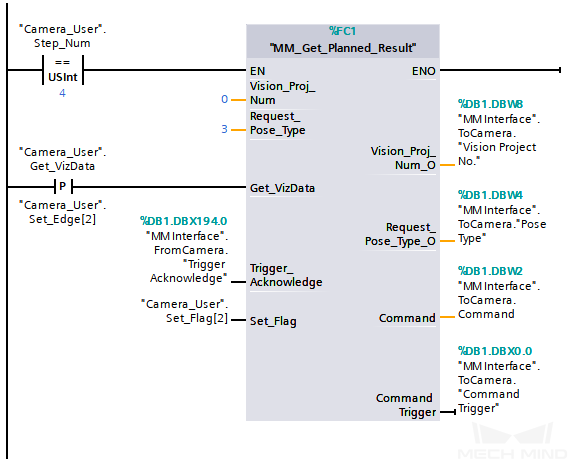
The example above indicates that "Camera_User".Step_Num is set to 4 and the "MM_Get_Planned_Result" feature is enabled. At this point, Vision_Proj_Num is 0. When a rising edge occurs on "Camera_User".Get_VizData, the waypoint data output from the Mech-Viz project is retrieved, with the pose type of the waypoints set to TCP. When the value of Target IsVisualMove is 1, it indicates that the waypoint obtained from the vision system is a Vision Move waypoint. Data output by the Vision Move Step is stored in VisualMove Planning Result, data output by the custom ports is stored in Custom Vision Output.