Siemens PLC Client–Siemens SIMATIC S7 PLC Functions
This topic introduces the functions for Siemens PCL Snap 7 communication between a Siemens SIMATIC S7 PLC and Mech-Mind Software Suite.
Function Descriptions
Start Mech-Vision Project
This function is used for applications that use Mech-Vision but not Mech-Viz. This function starts the Mech-Vision project that executes image capturing and performs vision recognition.
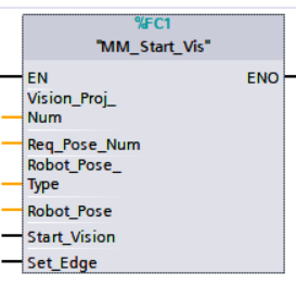
Parameters
Input parameters:
-
Vision_Proj_Num: Mech-Vision project ID, which is the number before the project name in the Project List panel in Mech-Vision;
-
Req_Pose_Num: The number of vision points that Mech-Vision is requested to send, from 1 to 20, where 0 indicates “send all”;
-
Robot_Pose_Type: The type of robot pose to input to Mech-Vision. The value range is 0–3;
-
Robot_Pose: The pose received from the robot, value depends on the value of Robot_Pose_Type. Data type: two-dimensional array [0..1, 0..5] of Real, array[0] is joint positions and array[1] is flange pose;
The following table explains the relationship between Robot_Pose_Type and Robot_Pose.
| Robot_Pose_Type value | Robot_Pose value | Description | Applicable Scenarios |
|---|---|---|---|
0 |
0, 0, 0, 0, 0, 0 |
No need to input robot pose to Mech-Vision |
Project is in the eye-to-hand mode. If the “Path Planning” Step is used in the Mech-Vision project, the planned path starts at the Home point set in the path planning tool. |
1 |
Current joint positions and flange pose of the robot |
Robot joint positions and flange pose must be input to Mech-Vision |
Project is in the eye-in-hand mode. Applicable to most robots (excluding truss robots). |
2 |
Current flange pose of the robot |
Robot flange pose must be input to Mech-Vision |
Project is in the eye-in-hand mode. The robot has no joint positions and only flange pose (such as truss robots). |
3 |
Joint positions of the start point of the planned path |
The joint positions of the path start point must be input to Mech-Vision |
Project is in the eye-to-hand mode and the Mech-Vision project contains the “Path Planning” Step, whose start point needs to be set from the robot side. |
-
Start_Vision: Trigger the start of the Mech-Vision project at the rising edge;
-
Set_Edge: Store the value of Start_Vision in the last cycle to prevent unnecessary repetition of triggering.
Parameters in data returned:
-
Status_Code: If there is no error, status code 1102 will be returned. Otherwise, the corresponding error code will be returned.
Example
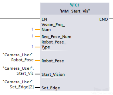
Example Description
When “Camera_User”.Start_Vis is at the rising edge, this example runs Mech-Vision project No.1, asks the Mech-Vision project to send over 1 vision point, and sends the robot joint positions when the Mech-Vision project is started as the image-capturing pose to Mech-Center.
Get Vision Target(s)
This function is used for applications that use Mech-Vision but not Mech-Viz. It obtains the vision result from the corresponding Mech-Vision project.
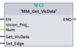
Parameters
Input parameters:
-
Vision_Proj_Num: Mech-Vision project ID, which is the number before the project name in the Project List panel in Mech-Vision;
-
Get_VisData: Obtain vision points from Mech-Vision project when a rising edge occurs;
-
Set_Edge: Store the value of Start_Vision in the last cycle to prevent unnecessary repetition of triggering.
Parameters in data returned:
-
Status code: If there is no error, status code 1100 will be returned. Otherwise, the corresponding error code will be returned;
-
Status of Pose Sent: 1 indicates that the pose data written in are new. After PLC reads the pose data, please reset this register;
-
Number of Pose Sent: Store the number of vision points returned. Range: [1, 20];
-
Target_Pose: Store the waypoint poses sent by Mech-Vision as TCPs;
-
Target_Label: Store the integer labels corresponding to the poses. Labels are set in Mech-Vision. The returned values are integers.
Example
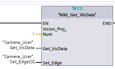
Example Description
When “Camera_User”.Get_VisData is at the rising edge, this example obtains the vision result from Mech-Vision project No.1.
Switch Mech-Vision Recipe
This function specifies which parameter recipe of the Mech-Vision project to use. Parameter recipes can be used to switch parameter settings, including point cloud model for matching, ROI, confidence threshold, etc, in the same Mech-Vision project when it is used to recognize different workpieces. This function must be called BEFORE MM_Start_Vis.
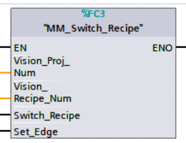
Parameters
Input parameters:
-
Vision_Proj_Num: Mech-Vision project ID, which is the number before the project name in the Project List panel in Mech-Vision;
-
Vision_Recipe_Num: The ID of a parameter recipe in the Mech-Vision project. Value range: 1 to 99;
-
Switch_Recipe: Switch the parameter recipe used by the Mech-Vision project when a rising edge occurs;
-
Set_Edge: Store the value of Start_Vision in the last cycle to prevent unnecessary repetition of triggering.
Parameters in data returned:
-
Status_Code: If there is no error, status code 1107 will be returned. Otherwise, the corresponding error code will be returned.
Example
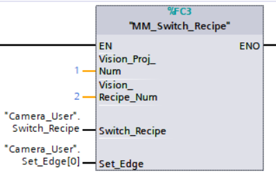
Example Description
When “Camera_User”.Switch_Recipe is at the rising edge, this example switches the parameter recipe used to No.2 in Mech-Vision project No.1.
Get Result of Step “Path Planning” in Mech-Vision
After calling MM_Start_Vis, call this function to obtain the collision-free picking path planned by the “Path Planning” Step in the Mech-Vision project.
When using this function, set the Port Type parameter of the “Procedure Out” Step in the Mech-Vision project to “Predefined (robot path)”.
| Before executing this function, please set Req_Pose_Num in MM_Start_Vis to 0 to reduce the times of execution of this function. If Req_Pose_Num in MM_Start_Vis is set to 1, then every time this function is executed, only 1 waypoint is returned, and this function must be executed multiple times to obtain all the waypoints. |
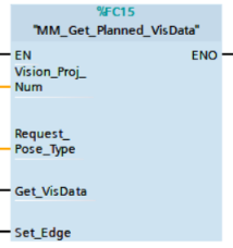
Parameters
Input parameters:
-
Vision_Proj_Num: Mech-Vision project ID, which is the number before the project name in the Project List panel in Mech-Vision;
-
Request_Pose_Type: Specify the type of waypoint pose returned by the “Path Planning” Step;
-
1: The waypoint poses are returned in the form of joint positions (JPs). -
2: The waypoint poses are returned in the form of tool center point (TCP).
-
| Request_Pose_Type and Robot_Pose_Type in the MM_Start_Vis and MM_Start_Viz functions correspond to the same Pose Type parameter in the Mech-Mind Interface data block. If the set values are different, they cannot take effect at the same time. |
-
Get_VisData: Obtains the planned path from the “Path Planning” Step in Mech-Vision at the rising edge;
-
Set_Edge: Store the value of Get_VisData in the last cycle to prevent unnecessary repetition of triggering.
Parameters in data returned:
-
Status_Code: If there is no error, status code 1103 will be returned. Otherwise, the corresponding error code will be returned;
-
Status of Pose Sent: 1 means that the written pose data is new data. After PLC reads the pose data, please reset this register;
-
Number of Pose Sent: Store the number of received waypoints sent by Mech-Vision, from 1 to 20;
-
Index of Vision Move: Store the position of the Vision Move waypoint in the path;
-
Target_Pose: Store the received waypoint poses in the form of joint positions or the XYZ Euler angles, depending on the input parameter Request_Pose_Type;
-
Target Label: Store the integer labels corresponding to the poses. Labels are set in Mech-Vision;
-
Speed_Percentage: Store the velocity settings corresponding to the poses.
Example
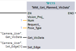
Example Description
When Camera_User.Get_VisData is at the rising edge, this example obtains the planned path from Mech-Vision No.1 in the form of joint positions.
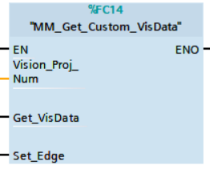
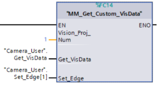
Get Vision Result from Mech-Vision
This function is used for applications that use Mech-Vision but not Mech-Viz. It obtains the vision result from the corresponding Mech-Vision project.
Parameters
Input parameters:
-
Vision_Proj_Num: Mech-Vision project ID, which is the number before the project name in the Project List panel in Mech-Vision;
-
Get_VisData: Obtain vision points from Mech-Vision project when a rising edge occurs;
-
Set_Edge: Store the value of Get_VisData in the last cycle to prevent unnecessary repetition of triggering.
Parameters in data returned:
-
Status_Code: If there is no error, status code 1100 will be returned. Otherwise, the corresponding error code will be returned;
-
Status of Pose Sent: 1 means that the written pose data is new data. After PLC reads the pose data, please reset this register;
-
Number_of_Pose_Sent: Store the number of vision points returned, from 1 to 20;
-
Target Pose: Store the waypoint poses sent by Mech-Vision as TCPs;
-
Target Label: Store the integer labels corresponding to the poses. Labels are set in Mech-Vision;
-
Custom Data Output: The custom data for the corresponding port of custom data type on Step “Procedure Out”. The custom data parameters are arranged in alphabetical order A–Z by port name.
Example
Example Description
When “Camera_User”.Get_VisData is at the rising edge, this example obtains the vision result from Mech-Vision project No.1.
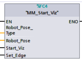
Start Mech-Viz Project
This function is for applications that use both Mech-Vision and Mech-Viz. It runs the corresponding Mech-Viz project (which triggers the corresponding Mech-Vision project to run), and then plans the path for picking.
Parameters
Input parameters:
-
Robot_Pose_Type: The type of robot pose to input to Mech-Viz. The value range is 0–2;
-
Robot_Pose: The pose received from the robot, value depends on the value of Robot_Pose_Type. Data type: two-dimensional array [0..1, 0..5] of Real, array[0] is joint positions and array[1] is flange pose;
The following table explains the relationship between Robot_Pose_Type and Robot_Pose.
| Robot_Pose_Type value | Robot_Pose value | Description | Applicable Scenarios |
|---|---|---|---|
0 |
0, 0, 0, 0, 0, 0 |
No need to input robot pose to Mech-Viz. The simulated robot in Mech-Viz moves from JPs = [0, 0, 0, 0, 0, 0] to the first waypoint. |
Project is in the eye-to-hand mode. This setting is not recommended. |
1 |
Current joint positions and flange pose of the robot |
Robot joint positions and flange pose must be input to Mech-Viz. The simulated robot in Mech-Viz moves from the input JPs to the first waypoint. |
This setting is recommended for projects in the eye-in-hand mode. |
2 |
Specific joint positions of the robot |
The robot joint positions of a point determined by teaching must be input to Mech-Viz. The input joint positions are used to trigger Mech-Viz to plan the next path in advance while the robot is not in the camera capture region, as shown below. The simulated robot in Mech-Viz moves from the input joint positions to the first waypoint. |
This setting is recommended for projects in the eye-to-hand mode. |
|
The reason for setting Robot_Pose_Type to 2 when the project is in the eye-to-hand mode:
In the eye-to-hand mode, the camera can perform image capturing for the next round of path planning before the robot returns to the camera capture region and picking region, shortening the cycle time. If Robot_Pose_Type is set to 1, the robot’s current pose is sent to Mech-Viz. The simulated robot will move from the input pose to the first waypoint in the planned path, while the real robot might move to another point first, and then move to the first waypoint. Therefore, the path of the real robot may contain unpredicted collisions, leading to safety hazards. In conclusion, Robot_Pose_Type should be set to 2 for projects in the eye-to-hand mode. 
|
-
Start_Viz: Triggers Mech-Viz project to run at the rising edge;
-
Set_Edge: Store the value of Start_Vision in the last cycle to prevent unnecessary repetition of triggering.
Parameters in data returned:
-
Status_Code: If there is no error, status code 2103 will be returned. Otherwise, the corresponding error code will be returned.
Example
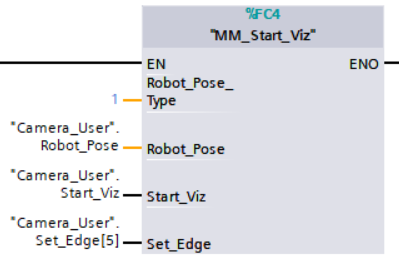
Example Description
When the variable “Camera_User”.Start_Viz is at the rising edge, this example runs the corresponding Mech-Viz project, and sends the current joint positions of the robot to Mech-Center.
StopMech-Viz Project
This function is used to stop Mech-Viz project.

Parameters
Input parameters:
-
Stop_Viz: Stops the execution of the Mech-Viz project at the rising edge;
-
Set_Edge: Store the value of Start_Vision in the last cycle to prevent unnecessary repetition of triggering.
Parameters in data returned:
-
Status_Code: If there is no error, status code 2104 will be returned. Otherwise, the corresponding error code will be returned.
Example
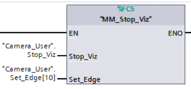
Example Description
When “Camera_User”.Stop_Viz is at the rising edge, this example stops the execution of the Mech-Viz project.
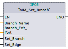
Select Mech-Viz Branch
This function is used to select along which branch the Mech-Viz project should proceed. Such branching is achieved by adding Branch by Msg Step(s) to the project. This function specifies which exit port such Step(s) should take. MM_START_VIZ must be called BEFORE this job. When the next Step to be executed in Mech-Viz is a Branch by Msg Step, the system will wait for this function to send the exit port number by the Command 203.
Parameters
Input parameters:
-
Branch_Name: Step ID of the Branch by Msg Step, which is a positive integer.
-
Branch_Exit_Port: The number of the exit port to take, from 1 to 99.
-
Set_Branch: The trigger signal for setting the branch. The rising edge does the trigger;
-
Set_Edge: Store the value of Start_Vision in the last cycle to prevent unnecessary repetition of triggering.
Parameters in data returned:
-
Status_Code: If there is no error, status code 2105 will be returned. Otherwise, the corresponding error code will be returned.
Example
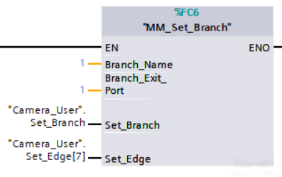
Example Description
When Camera_User.Set_Branch is at the rising edge, this example tells Mech-Viz to take exit port 1 for the Branch by Msg Step whose Step ID is 1.
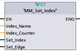
Set Move Index
This function sets the value for the Current Index parameter of Steps. Steps that have this parameter include Move by List, Move by Grid, Custom Pallet Pattern, and Smart Pallet Pattern. MM_Start_Viz must be called BEFORE this function.
Parameters
Input parameters:
-
Index_Name: Step ID of the Step with the index parameter, which is a positive integer.
-
Index_Counter: The index value that should be set the next time this Step is executed. When this function is sent, the current index value in Mech-Viz will become the parameter value minus 1. When the Mech-Viz project runs to the Step specified by this function, the current index value in Mech-Viz will be increased by 1 to become the parameter’s value.
-
Set_Index: The trigger signal to set the index. The rising edge does the trigger.
-
Set_Edge: Store the value of Start_Vision in the last cycle to prevent unnecessary repetition of triggering.
Parameters in data returned:
-
Status_Code: If there is no error, status code 2106 will be returned. Otherwise, the corresponding error code will be returned.
Example
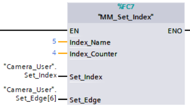
Example Description
When “Camera_User”.Set_Index is at the rising edge, this example sets the Current Index value to 3 for the Step in the Mech-Viz project whose Step ID is 5. When the Step is executed, the Current Index value will be added 1 and become 4.
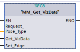
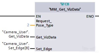
Get Planned Path
This function obtains the planned path from Mech-Viz.
Parameters
Input parameters:
-
Request_Pose_Type: Specify the type of waypoint pose returned;
-
The pose type returned by Mech-Viz is joint positions;
-
The pose type returned by Mech-Viz is TCPs.
-
-
Get_VizData: Obtains the planned path from Mech-Viz at the rising edge;
-
Set_Edge: Store the value of Start_Vision in the last cycle to prevent unnecessary repetition of triggering.
Parameters in data returned:
-
Status_Code: If there is no error, status code 2100 will be returned. Otherwise, the corresponding error code will be returned;
-
Status of Pose Sent: 1 indicates that the pose data written in are new. After PLC reads the pose data, please reset this register;
-
Number_of_Pose_Sent: Store the number of waypoints received from Mech-Viz. Range: [1, 20];
-
Index of Vision Move: Store the position of the Vision Move waypoint in the path;
-
Target_Pose: Store the received waypoint poses in the form of joint positions or the XYZ Euler angles, depending on the pose type set by Command 205;
-
Target_Label: Store the integer labels corresponding to the poses. Labels are set in Mech-Vision. The returned values are integers;
-
Speed Percentage: Store the velocity settings corresponding to the poses.
Example
Example Description
When “Camera_User”.Get_VizData is at the rising edge, this example obtains the planned path from Mech-Viz in the form of TCPs.
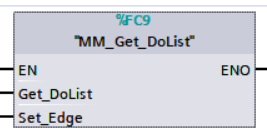
Get DO Signal List
This function obtains the planned DO Signal list for controlling multiple sections of a sectioned vacuum gripper. MM_Get_VizData must be executed BEFORE this function.
Please configure the Mech-Viz project based on the example project in XXXX/Mech-Center-xxx/tool/viz_project/suction_zone, and set the suction cup configuration file in the project.
|
Parameters
Input parameters:
-
Get_DoList: Obtain the planned DO signal list from Mech-Viz at the rising edge;
-
Set_Edge: Store the value of Start_Vision in the last cycle to prevent unnecessary repetition of triggering.
Parameters in data returned:
-
Status_Code: If there is no error, 2102 will be returned. Otherwise, the corresponding error code will be returned.
-
DO: The sixty-four DO signal values returned by executing this command. A valid DO value is in the range of [0, 999], and -1 is a placeholder value.
Example
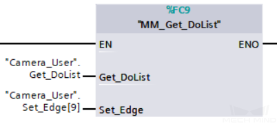
Example Description
In this example, when the parameter “Camera_User”.Get_DoList has a rising edge, the DO values from Mech-Vizll be stored in the DO list.
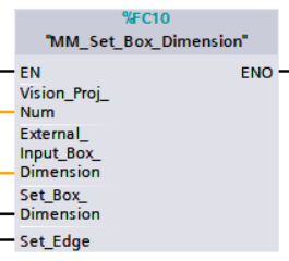
Input Object Dimensions to Mech-Vision
This function dynamically inputs object dimensions into the Mech-Vision project. This function must be called BEFORE “mm_start_vis”.
Parameters
Input parameters:
-
Vision_Proj_Num: Mech-Vision project ID, which is the number before the project name in the Project List panel in Mech-Vision;
-
External_Input_Box_Dimension: The 3D dimensions to input to the project in the unit of mm. The data type is Array[0..2] of Real;
-
Set_Box_Dimension: Inputs the object dimensions in the Mech-Vision project dynamically at the rising edge;
-
Set_Edge: Store the value of Start_Vision in the last cycle to prevent unnecessary repetition of triggering.
Parameters in data returned:
-
Status_Code: If there is no error, 1108 will be returned. Otherwise, the corresponding error code will be returned.
Example
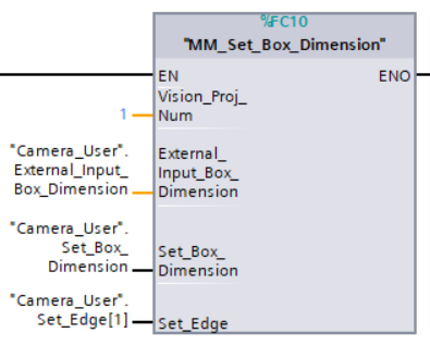
Example Description
In this example, when the parameter “Camera_User”.Set_Box_Dimension has a rising edge, the dimensions read by Step “Read Object Dimensions” will be set to the value of External_Input_Box_Dimension.
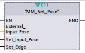
Input TCP to Mech-Viz
Input poses in TCP dynamically. Work with Step “external_move” in Mech-Viz.
Please deploy the project based on the template project at XXXX{product-center}-xxx\tool\viz_project\outer_move, and put the External Move Step to a proper position in the workflow. This function must be called BEFORE “MM_Start_Viz”.
|
Parameters
Input parameters:
-
External_Input_Pose: The parameter stores the TCP data to be sent to Mech-Viz. The data type is Array[0..5] of Real;
-
Set_Input_Pose: Input the TCP data to the External Move Step at the rising edge;
-
Set_Edge: Store the value of Start_Vision in the last cycle to prevent unnecessary repetition of triggering.
Parameters in data returned:
-
Status Code: If there is no error, *2107 *will be returned. Otherwise, the corresponding error code will be returned.
Example
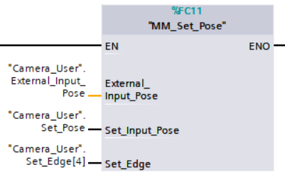
Example Description
In this example, when the parameter “Camera_User”.Set_Input_Pose has a rising edge, the data in External_Input_Pose will be sent to Step “outer_move” in Mech-Viz.
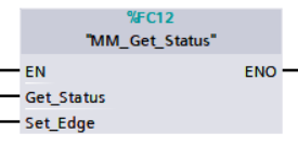
Get Software Status
This function is for obtaining the running status of Mech-Vision, Mech-Viz, Mech-Center (at present, only whether Mech-Vision is ready to start running the project can be checked).
Parameters
Input parameters:
-
Get_Status: Check whether Mech-Vision is ready to run projects at the rising edge;
-
Set_Edge: Store the value of Start_Vision in the last cycle to prevent unnecessary repetition of triggering.
Parameters in data returned:
-
Status code: Represent the software status.
Example
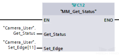
Example Description
In this example, when the parameter “Camera_User”.Get_Status has a rising edge. The software running status will be checked and the result will be stored in the parameter “Status code”.
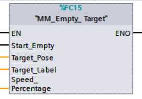
Clear Waypoint Data
This function clears the obtained data stored in Target_Pose, Target_Label, and Speed_Percentage.
Parameters
Input parameters:
-
Start_Empty: Clear the data stored in Target_Pose, Target_Label, and Speed_Percentage at the rising edge;
-
Target_Pose: Obtained waypoint pose data;
-
Target_Label: Obtained waypoint label;
-
Speed_Percentage: Obtained non-zero speed parameters of waypoints.
Example
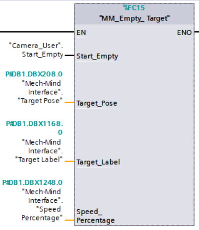
Example Description
In this example, when the parameter “Camera_User”.Start_Empty is set to 1, the acquired data in Target Pose, Target Label, Speed Percentage will be cleared.
Appendix
Description of the Status Codes
Please refer to Status Codes and Troubleshooting for detailed information.